Collecting material-distributing device

A technology of integrated variable material distributor and material distribution rod, which is applied in the field of integrated variable material distributor, can solve the problems of uneven feeding of the blanking guide column and dead angle of the integrated variable material distributor, so as to solve the problem of uneven feeding , Improve the uniformity characteristics, eliminate the effect of the possibility of dead ends in circulation

Inactive Publication Date: 2015-09-09
ANHUI SUNMIRO AGRI TECH
View PDF7 Cites 2 Cited by
  • Summary
  • Abstract
  • Description
  • Claims
  • Application Information

AI Technical Summary

Benefits of technology

This new design allows material inside slowly moving containers (such as carts) can be passed smoothly without any problems or issues that may occur during their passage due to accumulation on certain parts of these systems' surfaces. It also ensures even distribution of different types of products throughout this system by creating a circular flow pattern instead of just one single pathway. Overall, this technology helps improve efficiency and productivity while maintaining consistently high quality standards across various industries such as food production.

Problems solved by technology

This patented technical problem addressed by this patents relates to improving the flow of material during processing within various sections such as an oxygen generator or other manufacturing process where there are multiple steps involved with different stages for producing products. These processes require precise control over factors like temperature and humidity levels that affect how well everything works together. To address these issues, the inventors propose setting up a device called a set-variable feeder (SCF) on one side of the machine's slowering section nearer the end than usual while another area goes into the dryer section next. By allowing some parts of the SCF to move around without being stopped, any areas along which they can get stuck may be prevented from getting trapped inside due to gravity effects caused by convection currents generated by moving air past them.

Method used


Image

  • Collecting material-distributing device

Examples


Embodiment Construction

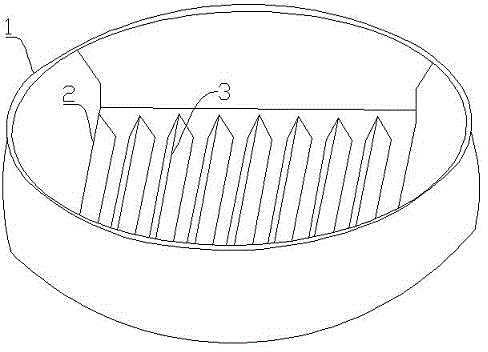
[0009] The specific embodiments of the present invention will be described in detail below in conjunction with the accompanying drawings.

[0010] Such as figure 1 As shown, this embodiment includes an upper circular feed port 1 and a lower square discharge port, the feed port 1 and the discharge port 2 are integrated, and several triangular prism distribution rods are arranged in the discharge port 2 3. Adopt the form of square circle transition to reduce the dead angle of material circulation. The inclined surface of the discharge port 2 is smooth, and the inclined surface flow angle can reach 133 degrees. , in order to increase its supporting strength, the interior is designed with a lined rib plate to increase the strength, and it is truly stable, durable, smooth and has no dead angle vacuum.

[0011] The triangular-shaped material distribution rod 3 is connected with the inner wall of the discharge port 2 through a rotating shaft. In order to prevent the material from being


PUM


Abstract

The invention discloses a collecting material-distributing device. The collecting material-distributing device comprises a circular feeding port (1) and a square discharge port (2) at the lower portion. The feeding port (1) and the discharge port (2) are integrated. The discharge port (2) is internally provided with multiple prismatoidal material-distributing rods (3). The collecting material-distributing device has following beneficial effects: an ingenious structure of a circular upper portion and a square lower portion is adopted; the device is connected with a cylindrical tempering bin body and a connecting flange of a square drying unit with the purpose of collecting material in the tempering bin body when material passes through the collecting material-distributing device; material enters the drying unit body from the middle portion of the tempering bin body so that a funnel-shaped circulation mode is formed; possibility of forming circulation dead angles at edges is avoided; and non-uniformity of all discharge guide columns in the drying unit body is solved in order to provide a guarantee for the evenness feature of a dryer.

Description


Claims


Application Information

Patent Timeline
Owner ANHUI SUNMIRO AGRI TECH
Why Eureka
Try Eureka