Seal and cover
a technology of sealing and cover, applied in the field of sealing, can solve the problems of deterioration of elastic parts, significant reduction of elasticity, and high risk of elastic members slipping back, and achieve the effect of improving both waterproof properties and performan
- Summary
- Abstract
- Description
- Claims
- Application Information
AI Technical Summary
Benefits of technology
Problems solved by technology
Method used
Image

Examples
first embodiment
[0045]the present invention will be described.
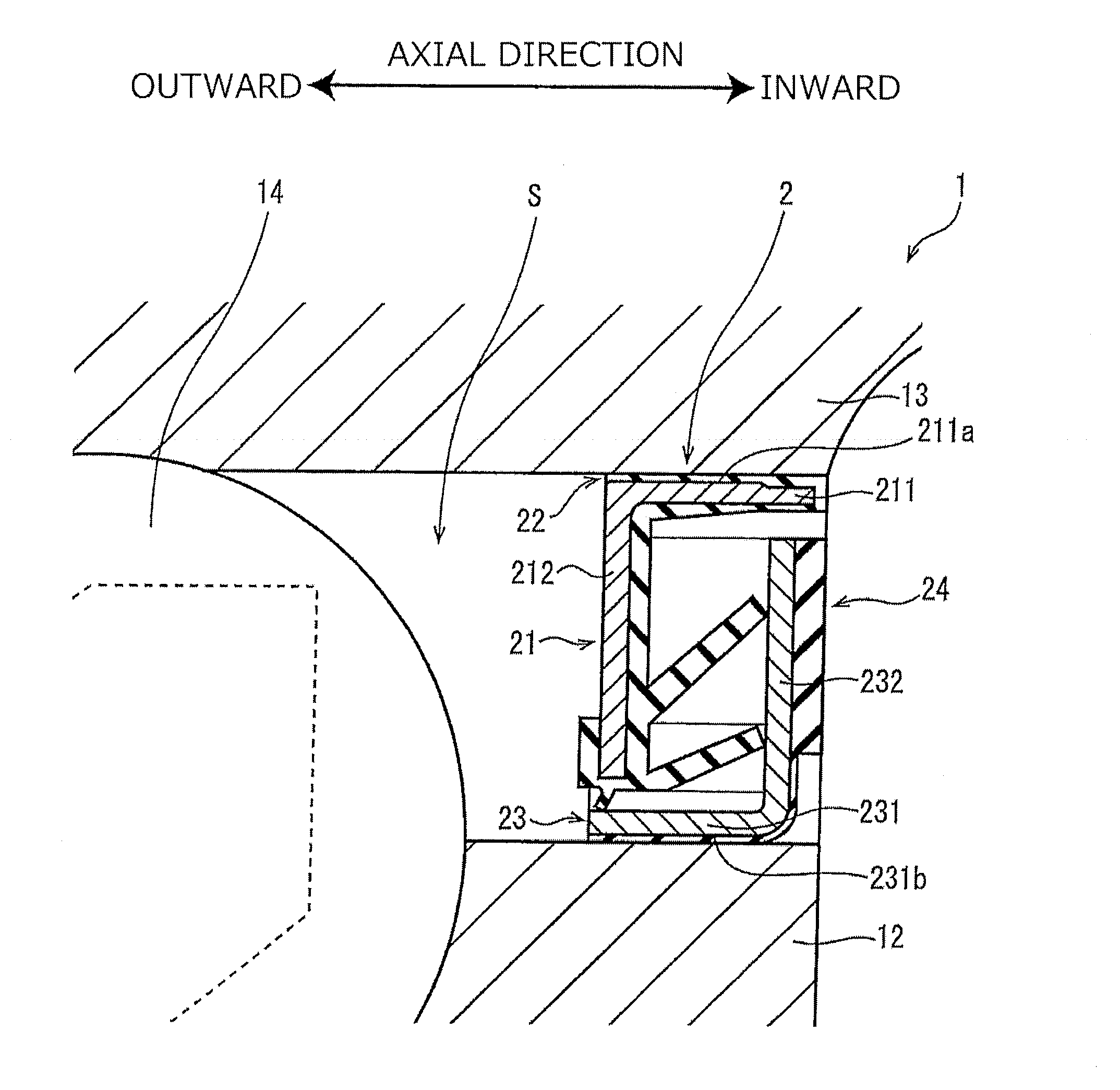
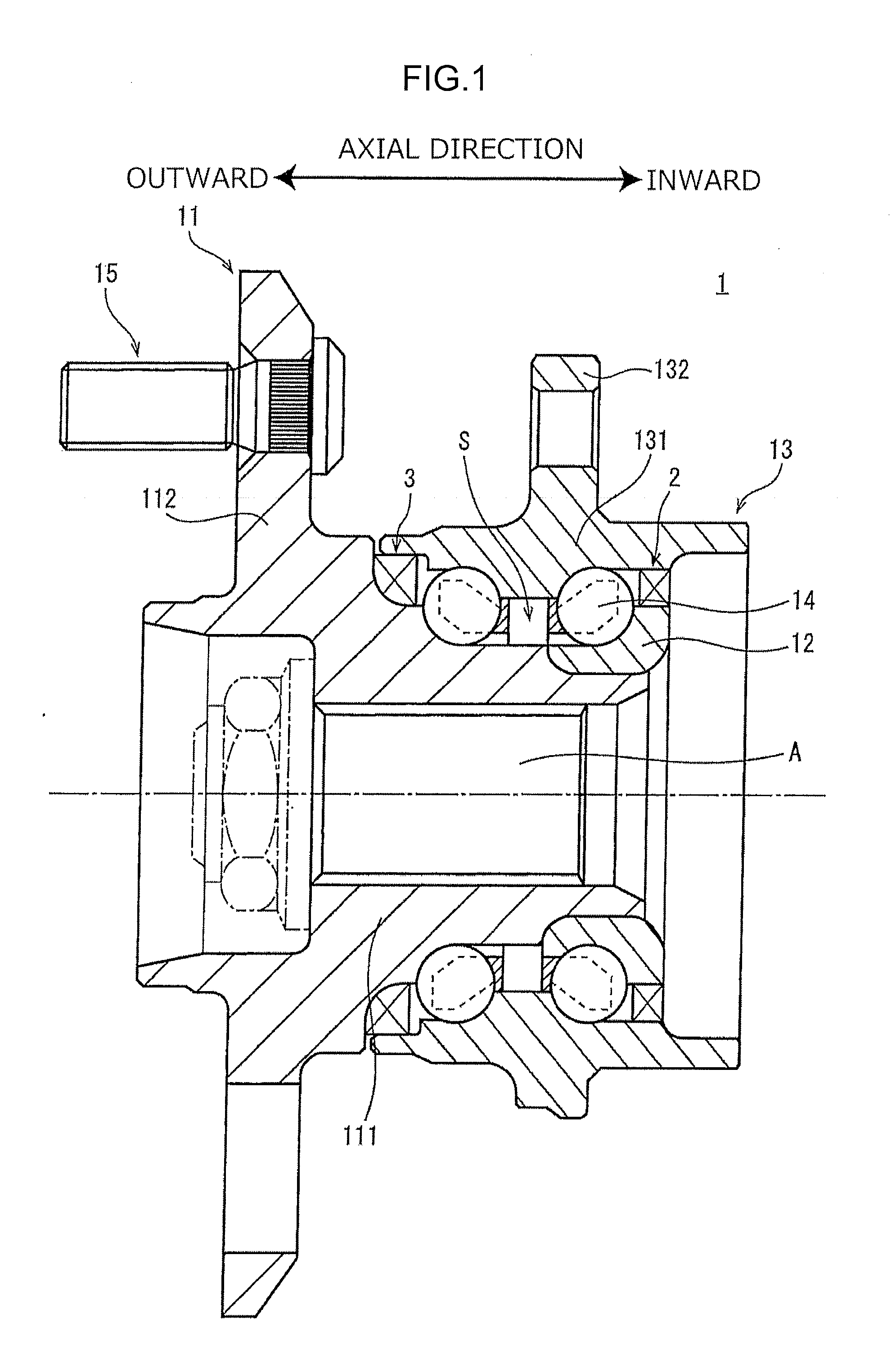
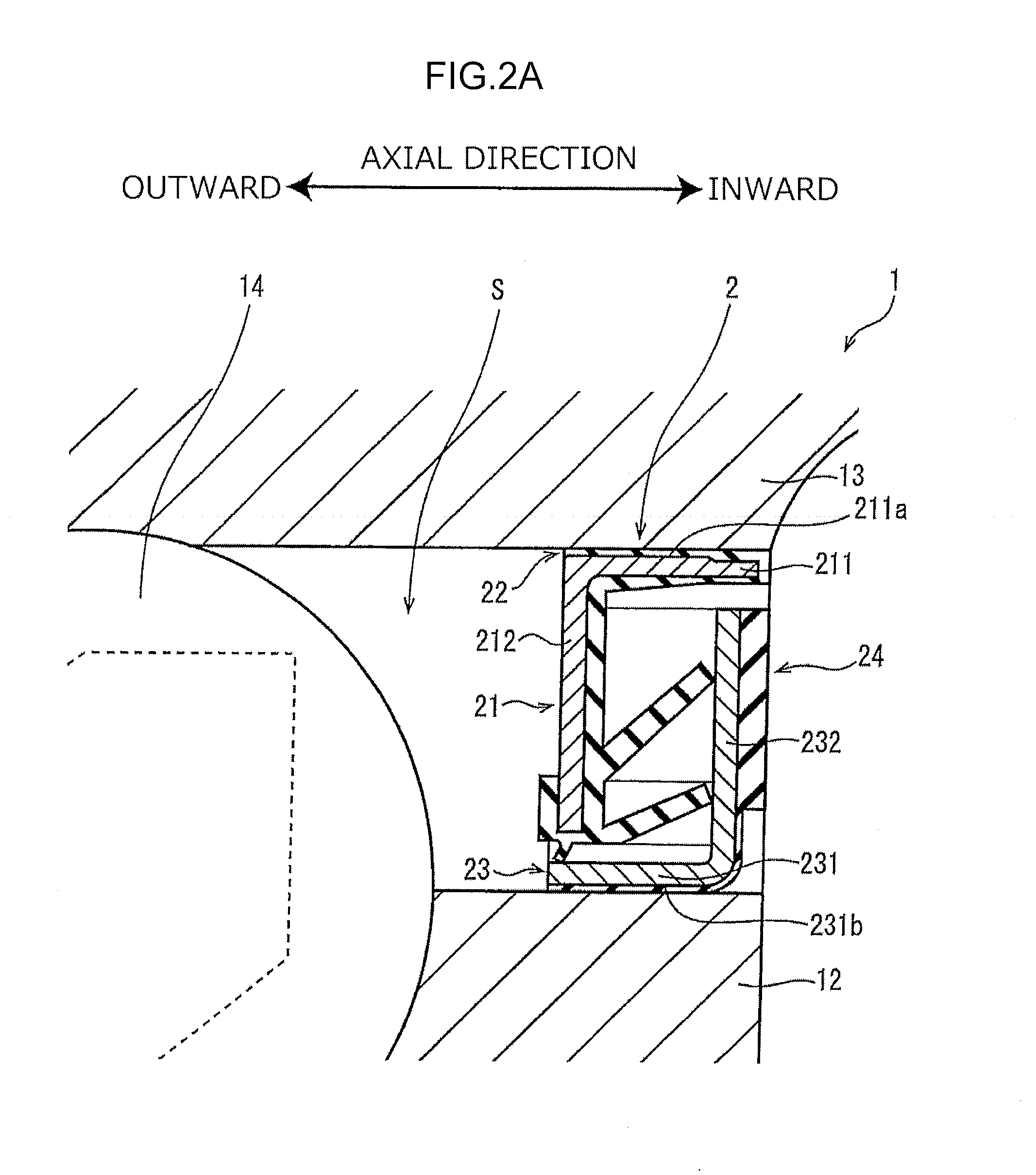
[0046]FIG. 1 is a vertical sectional view depicting a general configuration of a bearing apparatus 1 for a vehicle. In FIG. 1, seals 2 and 3 according to the first embodiment are attached to the bearing apparatus 1.
[0047]As depicted in FIG. 1, the bearing apparatus 1 includes a hub 11, an inner ring 12, an outer ring 13, and a plurality of rolling elements 14.
[0048]The hub 11 includes a generally cylindrical hub shaft 111 and a generally annular hub flange 112. An axle A is inserted into the hub 11. The hub shaft 111 and the axle A are fixed together. Thus, the hub 11 rotates with the axle A.
[0049]The hub flange 112 protrudes outward from an outer peripheral surface of the hub shaft 111 in a radial direction of the hub shaft 111. A disc wheel (not shown) and a brake disc (not shown) are fixed to the hub flange 112 using a plurality of fastening members 15.
[0050]The inner ring 12 is arranged at an end of the bearing apparatus 1 that is adjac
second embodiment
[0111]the present invention will be described below.
[0112]FIG. 4 is a vertical sectional view depicting a general configuration of a part of a bearing apparatus 1A for a vehicle. In FIG. 4, a cover 4 according to a second embodiment is attached to the bearing apparatus 1A. FIG. 5A is an enlarged view of a part of the bearing apparatus 1A to which the cover 4 is attached.
[0113]The bearing apparatus 1A is different from the bearing apparatus 1 according to the first embodiment in that the bearing apparatus 1A has a detection mechanism for the rotation speed of vehicle wheels. Members for detecting the rotation speed will be described below. The other members are denoted by the same reference numerals as those in the first embodiment and will not be described below.
[0114]As depicted in FIG. 4, the bearing apparatus 1A includes a pulsar ring 16, a rotation speed sensor 17, and a cap 18.
[0115]As depicted in FIG. 5A, the pulsar ring 16 includes a support ring 161 and a detection target membe
PUM
 Abstract
Description
Claims
Application Information
 - R&D Engineer
- R&D Manager
- IP Professional
- Industry Leading Data Capabilities
- Powerful AI technology
- Patent DNA Extraction
Browse by: Latest US Patents, China's latest patents, Technical Efficacy Thesaurus, Application Domain, Technology Topic.
© 2024 PatSnap. All rights reserved.Legal|Privacy policy|Modern Slavery Act Transparency Statement|Sitemap