Dust-free workshop
A technology for dust-free workshops and workshops, applied in measuring devices, instruments, and dispersed particle separation, etc., can solve the problems of high cost of dust removal and product outflow, and achieve the effect of reasonable design and low operating cost.
- Summary
- Abstract
- Description
- Claims
- Application Information
AI Technical Summary
Benefits of technology
Problems solved by technology
Method used
Image

Examples
Embodiment 1
[0025] In this embodiment, the structure of the present invention is described in detail with reference to the drawings.
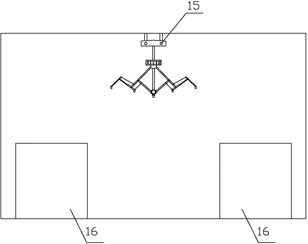
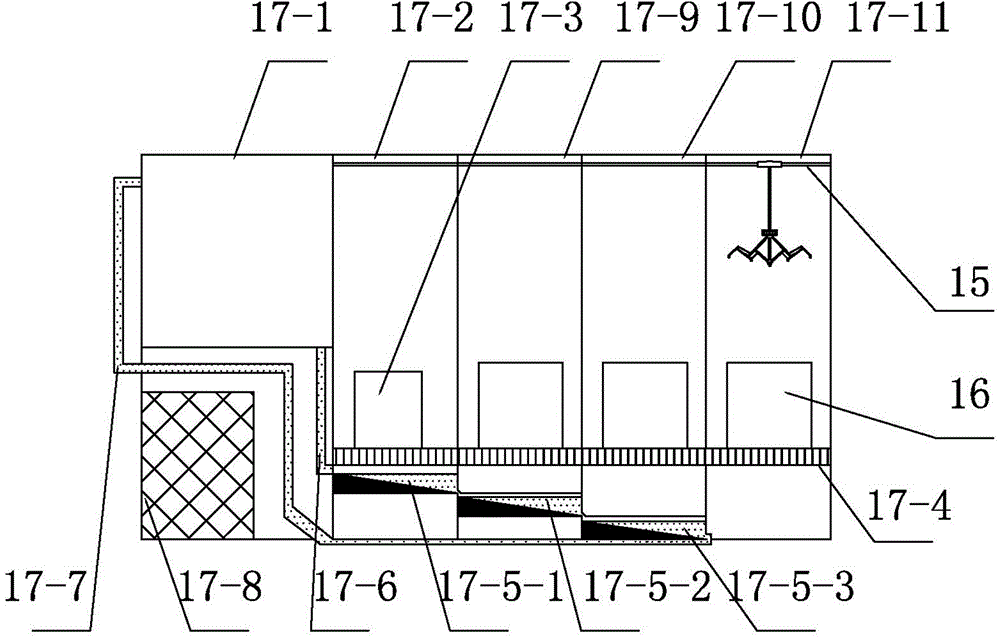
[0026] A clean room provided by the present invention includes a first clean room 17-2, a second clean room 17-9, a third clean room 17-10, a buffer room 17-11, and a controller 17- 8 and test stand 17-3. The dust-free level of the second clean room 17-9 and the third clean room 17-10 is lower than that of the first clean room 17-2, and the buffer room 17-11 is provided with a door suction dust removal device or an air shower. All use the dust-free equipment of common prior art. A dedusting water treatment system is provided under the floor 17-4 of the above-mentioned workshop, and a suspension-elevating local environment detection device that can move between the first to the third workshop is installed on the top of the above-mentioned workshop.
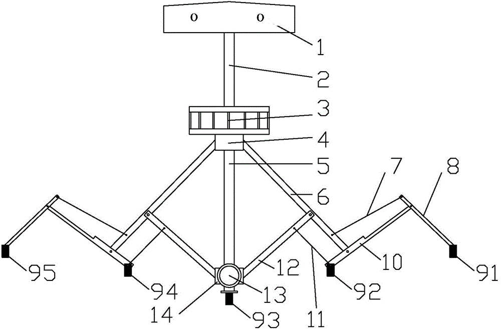
[0027] The detection device includes a body 1 and a controller that can move horizontally and is suspended on
Embodiment 2
[0038] The working principle of the dedusting water treatment system is that when people work on the test bench 17-3 or the workbench 16, the dust generated in the local range of human activities (the dust in the whole workshop is dedusted and ventilated through the original ventilation system of the workshop, but the local range dust is often adsorbed to the workshop floor and other parts of the machine, and cannot be effectively removed, and can only be vacuumed manually), under the action of gravity, it passes through multiple mesh holes set vertically in the workshop floor 17-4, and falls When entering the pool into the water, the dust generated by human activities in the air will be dropped into the water at any time, continuously reducing the dust in the air and greatly improving the quality of dust removal. Improved detection quality.
[0039] At the same time, under the influence of water gravity, water flows through the first water tank 17-5-1, the second water tank 517-
Embodiment 3
[0042] The working principle of the detection device is,
[0043] The first step is to install the local environment detection device.
[0044] In the second step, position determination, the controller 17-8 controls the body 1 to move on the guide rail 15 and move to the place to be observed. (The moving structure is a common technology, and the screw can be used to move, or the electric hoist can be used to move)
[0045] The third step is horizontal adjustment. The controller 17-8 first controls the motor 13 to drive the lower hinge plate 14 to rise or fall, adjust the expansion width of the multi-link assembly to a suitable position and lock it, so as to adapt to the gap between the workbenches 16 .
[0046] The fourth step is vertical adjustment, the controller 17-8 controls the electric screw rod 2 to stretch out downwards, and the proper position of the measuring detector will be landed. You can start testing.
[0047] Combining the dust removal water treatment system
PUM
 Abstract
Description
Claims
Application Information
 - R&D Engineer
- R&D Manager
- IP Professional
- Industry Leading Data Capabilities
- Powerful AI technology
- Patent DNA Extraction
Browse by: Latest US Patents, China's latest patents, Technical Efficacy Thesaurus, Application Domain, Technology Topic.
© 2024 PatSnap. All rights reserved.Legal|Privacy policy|Modern Slavery Act Transparency Statement|Sitemap