Combined septic tank

A septic tank and side plate technology, applied in the field of combined septic tanks, can solve the problems of inconvenient assembly and achieve the effect of convenient installation

Inactive Publication Date: 2015-09-16
湖州国盛环保工程有限公司
View PDF9 Cites 1 Cited by
  • Summary
  • Abstract
  • Description
  • Claims
  • Application Information

AI Technical Summary

Benefits of technology

The technology described involves assembling different parts with each other through an insertion process that makes it easier than previous methods like welding or gluing them into place. This allows for easy maintenance without having to be disassembleled during production or shipping.

Problems solved by technology

This patented describes how different parts can be combined into one unit called a septic tanks for use during medical procedures or other applications where wastewater needs to be collected safely from large areas without causing environmental pollution issues such as water contamination.

Method used


Image

  • Combined septic tank
  • Combined septic tank
  • Combined septic tank

Examples


Embodiment Construction

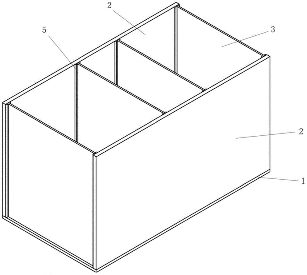
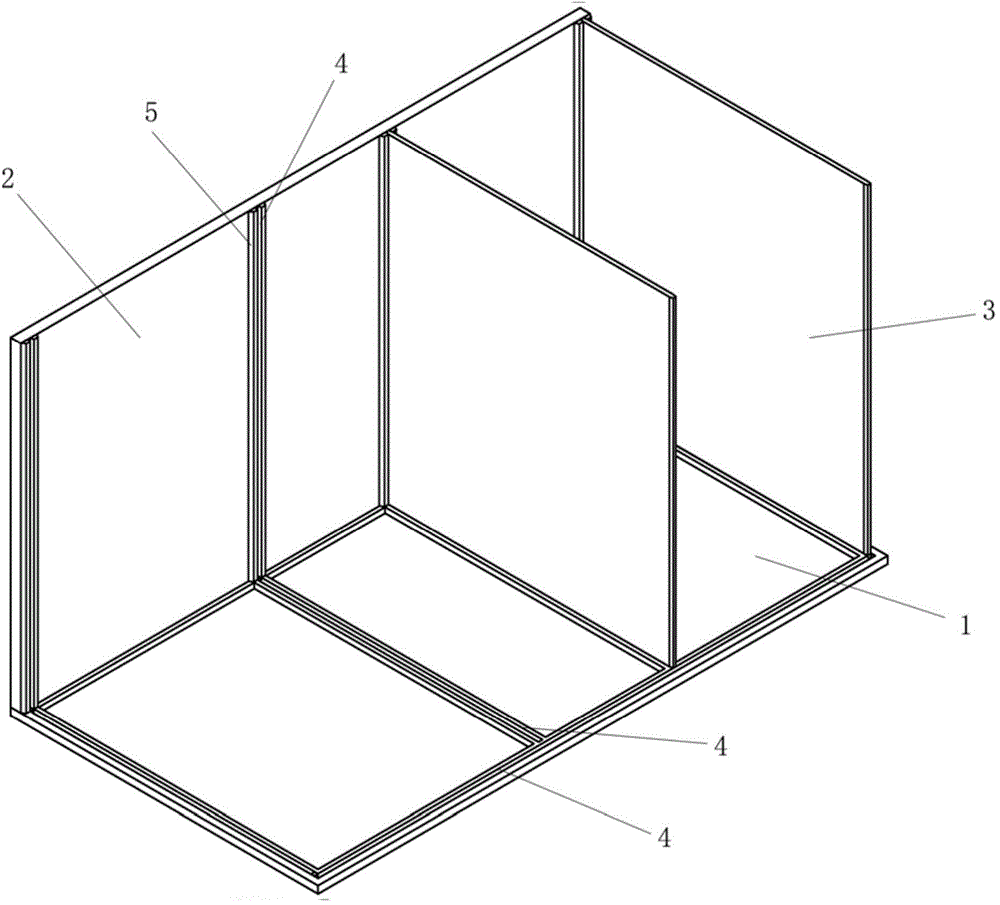
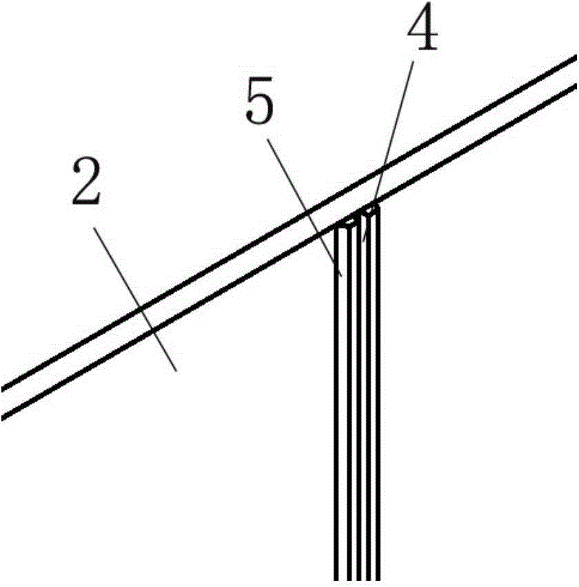
[0014] Such as Figures 1 to 3 Shown is a preferred embodiment of the combined septic tank of the present invention, the combined septic tank mainly includes a bottom plate 1, two side plates 2 and four partitions 3, the two side plates 2 are arranged on the top surface of the bottom plate 1, Two side plates 2 are arranged oppositely, and four partitions 3 are arranged between the two side plates 2, between the bottom plate 1 and the side plate 2, between the bottom plate 1 and the partition 3, and between the side plate 2 and the partition 3 Each side plate 2 is facing the other side plate 2 and is provided with a groove 4 at the position where each partition plate 3 is located, and the top surface of the bottom plate 1 is on each side. The positions of each partition 3 are also provided with grooves 4, the side of the partition 3 is stuck in the groove 4 of the side plate 2, and the bottom of the partition 3 is stuck on the top of the bottom plate 1 facing the position of the p


PUM


Abstract

The invention discloses a combined septic tank which is convenient for assembly. The combined septic tank comprises a bottom plate, two side plates and a plurality of partitions, wherein the two side plates are arranged on the top surface of the bottom plate and arranged in opposite; the partitions are arranged between the two side plates; one side of each side plate faced with the other side plate and the position of each partition are respectively provided with a groove; the top surface of the bottom plate is also provided with grooves in the position of each partition; the side part of each partition is clamped in each groove of the side plate; and the bottom end of each partition is clamped in the groove of the top surface of the bottom plate in the corresponding partition position.

Description


Claims


Application Information

Patent Timeline
Owner 湖州国盛环保工程有限公司
Why Eureka
Try Eureka