LED (Light-Emitting Diode) television two-in-one power supply circuit and LED television

A technology of LED TV and power supply circuit, which is applied in the direction of TV, color TV, color TV parts, etc. It can solve the problems of high cost, low efficiency of LED TV power supply circuit, and inability to protect devices, so as to achieve a small number and improve power supply Efficiency, the effect of reducing device cost

Active Publication Date: 2015-09-23
KONKA GROUP
View PDF4 Cites 33 Cited by
  • Summary
  • Abstract
  • Description
  • Claims
  • Application Information

AI Technical Summary

Problems solved by technology

[0005] In view of the deficiencies of the prior art above, the purpose of the present invention is to provide a two-in-one power supply circuit for LED TV and LE

Method used


Image

  • LED (Light-Emitting Diode) television two-in-one power supply circuit and LED television
  • LED (Light-Emitting Diode) television two-in-one power supply circuit and LED television
  • LED (Light-Emitting Diode) television two-in-one power supply circuit and LED television

Examples


Embodiment Construction

[0034] The invention provides a two-in-one power supply circuit for an LED TV and an LED TV. In order to make the object, technical solution and effect of the present invention more clear and definite, the present invention will be further described in detail below with reference to the accompanying drawings and examples. It should be understood that the specific embodiments described here are only used to explain the present invention, not to limit the present invention.

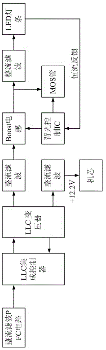
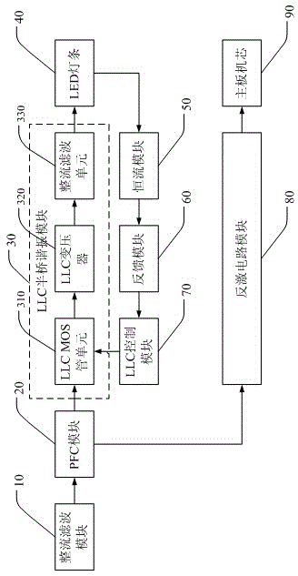
[0035] see figure 2 The two-in-one LED TV power supply circuit provided by the present invention includes a rectification and filtering module 10, a PFC module 20, a flyback circuit module 80, an LLC half-bridge resonant module 30, a constant current module 50, a feedback module 60 and an LLC control module 70.

[0036] The rectification and filtering module 10 rectifies and filters the alternating current, and outputs it to the PFC module 20; the PFC module 20 performs power factor correction on the rectifi


PUM


Abstract

The invention discloses an LED (Light-Emitting Diode) television two-in-one power supply circuit and an LED television. The LED television two-in-one power supply circuit comprises a rectifying and filtering module, a PFC (Positive Feedback Circuit) module, a reverse excitation circuit module, an LLC (Logical Link Control) half-bridge resonant module, a constant-current module, a feedback module and an LLC control module. Alternating current is partitioned into two paths after being rectified and filtered and corrected by the PFC module; one path is used for supplying power to a motherboard core through the reverse excitation circuit module; and the other path is used for supplying power to an LED light bar through the LLC half-bridge resonant module. Power is supplied separately with two paths since voltages needed by the LED light bar and the motherboard core are different, so that the power supply efficiency is increased, and the element cost is lowered. The LLC control module is fed back to the primary stage of an LLC transformer of the LLC half-bridge resonant module, so that the resonant groove state is monitored in real time, and complete protection is realized. Moreover, the transformer does not need to be driven, so that the quantity of safety devices is small.

Description


Claims


Application Information

Patent Timeline
Owner KONKA GROUP
Why Eureka
Try Eureka