Discharge lamp igniting device and light appliance

A lighting device and discharge lamp technology, applied in the direction of electric lamp circuit arrangement, lighting device, electric light source, etc., can solve the problems that the output of the inverter circuit 54 cannot be stabilized, the low power control of the discharge lamp cannot be expected, and the load circuit current cannot be obtained.

Inactive Publication Date: 2004-01-28
TOSHIBA LIGHTING & TECH CORP
View PDF3 Cites 3 Cited by
  • Summary
  • Abstract
  • Description
  • Claims
  • Application Information

AI Technical Summary

Problems solved by technology

With this circuit configuration, the current flowing through the saturable transformer Tr11 flows through the capacitor capacitor C12 and the aforementioned primary winding Tr12a, so in the load current detection circuit 24, the current flowing through the load circuit including the saturable transformer Tr11 cannot be obtained.
Therefore, although the current flowing through the fluorescent lamps FL1 and FL2 can be controlled to a constant value due to the change in the magnetic characteristics due to the self-heating of the saturable transformer Tr11, the current flowing through the load circuit cannot be controlled to a constant value.
[0012] That is, although the technique of Patent Document 1 can actually perform constant current control on the connected discharge lamp, it cannot expect low-power control on a different type of discharge lamp.
[0013] Furthermore

Method used


Image

  • Discharge lamp igniting device and light appliance
  • Discharge lamp igniting device and light appliance
  • Discharge lamp igniting device and light appliance

Examples


Embodiment Construction

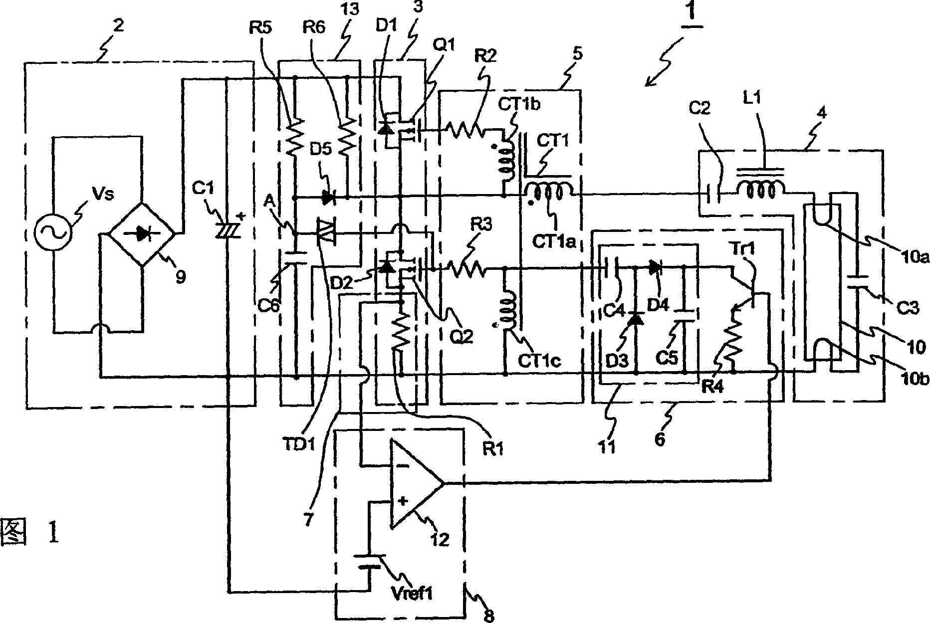
[0067] Hereinafter, one embodiment of the present invention will be described with reference to the drawings. First, a first embodiment of the present invention will be described.

[0068] Fig. 1 is a circuit diagram showing a discharge lamp lighting device according to a first embodiment of the present invention. The discharge lamp lighting device 1 has a DC power supply 2 , a switch circuit 3 , a load circuit 4 , a drive circuit 5 , magnetic energy control means 6 , current detection means, and current control means 8 .

[0069] The configuration of the DC power supply 2 includes a rectifier 9 connected to a commercial 100V low-frequency AC power supply Vs and a smoothing capacitor C1. The rectification device 9 is formed by a bridge full-wave rectification circuit, and its AC input terminal is connected to the low-frequency AC power supply Vs, and its DC output terminal is connected to the smoothing capacitor C1. The rectifying device 9 rectifies the AC voltage of the low-fr


PUM


Abstract

Provided is a discharge lamp lighting device and a light apparatus capable of stabilizing an output to a load circuit against a change in the temperature of a current transformer. The device comprises a driving circuit (5) equipped with a current transformer (CT1) having a detection winding (CT2a) to detect a current flowing in a load circuit (4) and positive feedback windings (CT1b, CT1c) which feedback currents to first and second switching means (Q1, Q2), respectively, by magnetic coupling, a magnetic energy control means (6) to control the magnetic energy of the current transformer (CT1), a current detecting means (7) to detect a mean value of an output current of a direct current power source (2) or a current flowing in a switching circuit (3), and a current control means (8) to control the magnetic energy control means (6) so that the mean value of the current falls on a preset value.

Description


Claims


Application Information

Patent Timeline
Owner TOSHIBA LIGHTING & TECH CORP
Why Eureka
Try Eureka