Vacuum permanent magnet energy conversion system

A technology of permanent magnetic energy and vacuum, applied in the direction of permanent magnetic clutches/brakes, electrical components, electromechanical devices, etc., can solve problems such as insufficient

Inactive Publication Date: 2018-10-23
江利
View PDF0 Cites 0 Cited by
  • Summary
  • Abstract
  • Description
  • Claims
  • Application Information

AI Technical Summary

Benefits of technology

This new technology allows for efficient conversion between different types of electrical power (magnetic or electric) by utilizing two sets of permanently excited iron-based materials called pigeons). These systems are designed differently from previous designs but still function well even at very small distances below them due to their unique properties such as gravity's ability to change direction when rotated around an axis.

Problems solved by technology

This patented technical problem addressed by this patents relates to how to efficiently utilizing magnetism's special properties while producing useful power from it without requiring external sources like batteries or windings.

Method used


Image

  • Vacuum permanent magnet energy conversion system

Examples


Embodiment Construction

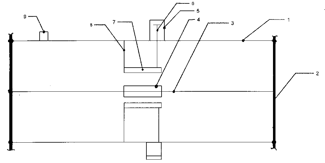
[0013] Refer to the attached drawings: The designed vacuum permanent magnet energy transformation system includes: a walking permanent magnet block 4 connected by a driving link 3, a reciprocating permanent magnet block 7 and a fixed outer frame 1, of which: fixed outer frame 1 and drive shaft 2 The drive shaft 2 is connected with the drive chain 3, the drive chain is connected with the walking permanent magnet block 4. The walking permanent magnet block 4. only travels in a straight line, the high pressure cylinder 5 is connected to the fixed frame 1, the piston connecting rod 6 is connected to the reciprocating permanent magnet block 4. The magnetic block 7 is connected, the reciprocating permanent magnet block 7 is connected with the movable permanent magnet block fixing rod 8, the movable permanent magnet block fixing rod is connected with the fixed outer frame 1, and the vacuum valve 9 is connected with the fixed outer frame 1.

[0014] When working, first fix two reciprocating


PUM


Abstract

The invention relates to a vacuum permanent magnet energy conversion system. The system comprises a walking permanent magnet block connected with a driving chain, permanent magnet blocks which performreciprocating motion, and a vacuum fixing outer frame; the walking permanent magnet block is installed on the driving chain and performs linear motion in the vacuum fixing outer frame; the reciprocating motion permanent magnet blocks are fixed side by side on two movable permanent magnet block fixing rods, so that a constant magnetic field can be formed between the two permanent magnet blocks; the linear motion walking permanent magnet block can pass a space between the two permanent magnets, so that the acting force of the constant magnetic field is changed; and the original attractive forceof the magnetic field is instantly changed to a repulsive force; the repulsive force of the magnetic field is used to push a piston rod in an air cylinder to compress air; and the attractive force ofthe magnetic field is used to drive the piston rod to return, so that the piston rod in the air cylinder retreats to be in an air intake state. According to the system, under a vacuum low-resistancecondition, the magnetic force can be converted into kinetic energy capable of working; and under the continuous action of a plurality of walking permanent magnet blocks, magnetic force energy can be applied to production and life.

Description


Claims


Application Information

Patent Timeline
Owner 江利
Why Eureka
Try Eureka