Main bearing assembly of wind generating set

A technology for wind turbines and main bearings, applied to wind turbine components, wind engines, engines, etc., can solve the problems of increasing machining costs and not being able to be used in generator direct drive units, and achieve low cost, light weight, Apply a wide range of effects

Inactive Publication Date: 2015-10-21
BEIJING SANLI XINNENG SCI & TECH
View PDF9 Cites 8 Cited by
  • Summary
  • Abstract
  • Description
  • Claims
  • Application Information

AI Technical Summary

Problems solved by technology

But the disadvantage of this kind of bearing seat is that the inclined connection surface will increase some machining costs
Fu...

Method used


Image

  • Main bearing assembly of wind generating set
  • Main bearing assembly of wind generating set
  • Main bearing assembly of wind generating set

Examples


Embodiment 1

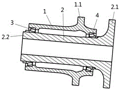
[0019] Attached figure 1 , 2 It is an embodiment of the present invention. The invention provides a main bearing assembly of a wind turbine generator set, comprising an outer shaft, an inner shaft, a front bearing and a rear bearing. The outer shaft is provided with an inner shaft, and a front bearing is provided between one end of the outer shaft and one end of the inner shaft. A rear bearing is arranged between the other end of the shaft and the other end of the inner shaft, one end of the inner shaft is provided with flange one, the other end is provided with flange two, and the outer shaft wall is provided with a connecting flange.

[0020] Further, the outer shaft is located between the outer shaft and the inner shaft, and one end with a rear bearing is provided with a connecting flange.

[0021] Further, the inner shaft is located between the outer shaft and the inner shaft, and one end of the rear bearing is provided with flange one, and the other end is provided with fl...

Embodiment 2

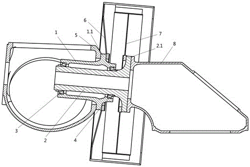
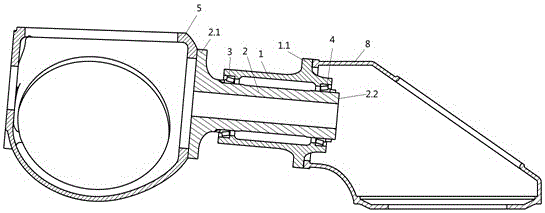
[0026] Attached image 3 In an embodiment of the present invention, a main bearing assembly of a wind turbine generator set of the present invention includes an outer shaft, an inner shaft, a front bearing and a rear bearing. The outer shaft is provided with an inner shaft, and one end of the outer shaft is connected to the inner shaft. A front bearing is provided between one end, and a rear bearing is provided between the other end of the outer shaft and the other end of the inner shaft. One end of the inner shaft is provided with flange one, the other end is provided with flange two, and the outer shaft wall is provided with a connection Flange.

[0027] Further, the outer shaft is located between the outer shaft and the inner shaft, and one end with a rear bearing is provided with a connecting flange.

[0028] Further, the inner shaft is located between the outer shaft and the inner shaft, and one end of the front bearing is provided with flange one, and the other end is provid...


PUM


Abstract

The invention relates to a transmission system structure of a wind generating set, and in particular to a main bearing assembly of the wind generating set. The main bearing assembly of the wind generating set comprises an outer shaft, an inner shaft, a front bearing and a back bearing; the inner shaft is arranged in the outer shaft, the front bearing is arranged between one end of the outer shaft and one end of the inner shaft, and the back bearing is arranged between the other end of the outer shaft and the other end of the inner shaft; and a first flange is arranged at one end of the inner shaft, a second flange is arranged at the other end of the inner shaft, and a connecting flange is arranged on the wall of the outer shaft. The main bearing assembly has the beneficial effects that the structure is simple, the weight is small, and the cost is low; and the main bearing assembly is wide in application scope, and can be used on the set, in a machine cabin, of a transmission system and can also be used on a direct drive set, between the machine cabin and an impeller, of a power generator.

Description

Technical field [0001] The invention relates to a transmission system structure for a wind power generating set, in particular to a main bearing assembly of a wind power generating set. Background technique [0002] The most commonly used main bearing for wind turbines is a spherical roller bearing. This type of bearing is a non-removable analysis bearing for the inner and outer rings. Only one bearing seat can be used for each bearing. The bearing seat structure is shown in CN203730577. Spherical roller bearings have axial clearance and cannot be positioned well in the axial direction. Therefore, many wind turbine manufacturers have proposed some new solutions. CN103518062 and CN204419878 use two single-row tapered roller bearings as main bearings. In order to ensure the coaxiality of the bearing housing holes, the bearing housings of the two bearings are designed as one body and are installed on the base by means of 4 feet. The above-mentioned 4-foot type bearing seat is not ...

Claims


Application Information

Patent Timeline
Patent Type & Authority Applications(China)
IPC IPC(8): F03D11/00
Inventor 李海开樊彦斌胡成明崔新维何家志
Owner BEIJING SANLI XINNENG SCI & TECH
Why Eureka
Try Eureka