Chopper-type direct current detection method and circuit

A technology of DC current and detection method, applied in the direction of using digital measurement technology for measurement, etc., can solve problems such as signal distortion, and achieve the effect of improving adaptability

Active Publication Date: 2015-10-21
武汉精能电子技术有限公司 +1
View PDF5 Cites 17 Cited by
  • Summary
  • Abstract
  • Description
  • Claims
  • Application Information

AI Technical Summary

Benefits of technology

This patented technology describes an improved way to detect AC currents without requiring extra parts or complicated processes. It achieves this through combining two different methods - one involves measuring small amounts of electrical energy from another object while keeping it stable during its passage over long periods (DC), and then averaging these measurements together to reduce unwanted interference. Another approach called direct choking type current measurement allows for precise adjustment of input impedance values based upon environmental factors like ambient temperatures. Overall, this new technique simplifies the process of creating accurate AC power systems at reduced costs.

Problems solved by technology

This patented technology describes an AC power system monitoring technique called Direct Current (DC) Signal Detection (DS). It involves connecting a shunted resistance into a line between two different components like a transformer or other electrical equipment. By measuring this connection's impedance at both ends, we can determine how well these connections are functioning properly without being influenced from external sources like lightning strikes or any environmental conditions affecting their performance. However, there may be some issues related to accurate measurement of large currents caused by smaller voltages present during normal operation. These include variations due to manufacture differences, component tolerances, thermal effects, etc., which makes precise measurements challenging even for skilled technicians who have been trained over time.

Method used


Image

  • Chopper-type direct current detection method and circuit
  • Chopper-type direct current detection method and circuit
  • Chopper-type direct current detection method and circuit

Examples


Embodiment Construction

[0046] In order to make the object, technical solution and advantages of the present invention clearer, the present invention will be further described in detail below in conjunction with the accompanying drawings and embodiments. It should be understood that the specific embodiments described here are only used to explain the present invention, not to limit the present invention. In addition, the technical features involved in the various embodiments of the present invention described below can be combined with each other as long as they do not constitute a conflict with each other.

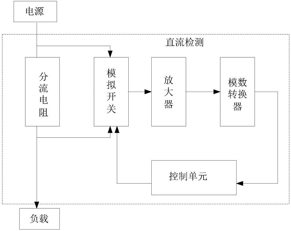
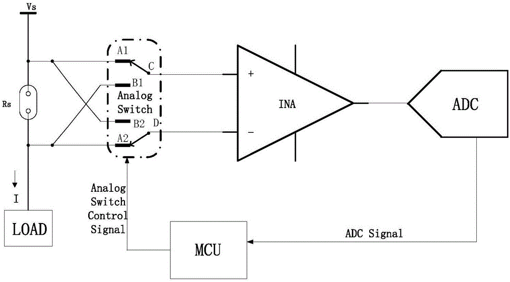
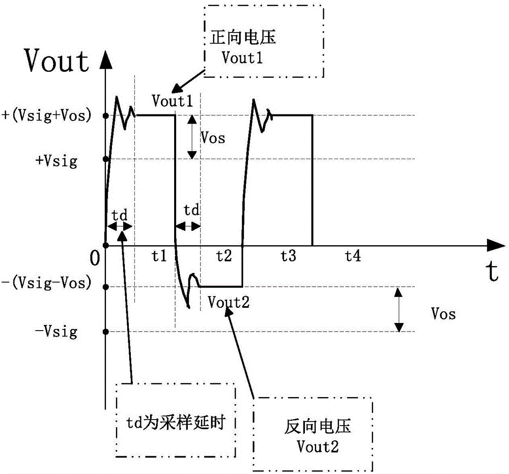
[0047] The chopper-type DC current detection circuit and method provided by the present invention collect the forward voltage and reverse voltage at both ends of the shunt resistor in real time, and calculate the average after subtracting the forward and reverse voltages in the same chopping cycle. Obtain the DC voltage detection value, and then further obtain the current detection value.

[0048]


PUM


Abstract

The invention discloses a chopper-type direct current detection method and a circuit. A forward voltage and a backward voltage of two ends of a shunt resistor are continuously collected in real time through a certain frequency. A sampling value of a first half of a chopper period and a sampling value of a second half of the chopper period in a same chopper period are calculated and influences of a low-frequency noise, an offset voltage and other noises on a detection result are eliminated. The detection circuit comprises a shunt resistor, a simulation switch, an amplifier, an analog-to-digital converter and a control unit. The simulation switch is connected in parallel to two ends of the shunt resistor. An input terminal of the amplifier is connected to an output terminal of the simulation switch. An input terminal of the analog-to-digital converter is connected to an output terminal of the amplifier. An input terminal of the control unit is connected to an output terminal of the analog-to-digital converter. An output terminal of the control unit is connected to a control signal input terminal of the simulation switch. On one hand, the control unit provides a digital signal to control switching of the simulation switch; on the other hand, according to digital forward and backward voltage signal, the control unit acquires a direct current detection value. A circuit structure provided in the invention is simple; test accuracy is high and cost is low.

Description


Claims


Application Information

Patent Timeline
Owner 武汉精能电子技术有限公司
Why Eureka
Try Eureka