Lubricating structure for output shaft of liquid booster pump

A technology of lubricating structure and output shaft, applied in lubricating parts, engine lubrication, lubricating oil control valve, etc., can solve the problems of low hydraulic pressure, long crankshaft, unable to obtain good spray effect, etc., to achieve extended use Long life, good lubrication effect

Inactive Publication Date: 2015-12-09
ZHONGHEYA
View PDF8 Cites 1 Cited by
  • Summary
  • Abstract
  • Description
  • Claims
  • Application Information

AI Technical Summary

Benefits of technology

This new design uses two parts - one called an input/output (I/O) section where there are three different sections: 1staryrils at top ends of the I/0 section act like bearings while 2ndaries located near bottom endes provide support for these components during operation. These features help reduce friction between them and prolong their lifespan.

Problems solved by technology

This patented technical solution described involves improving the performance and durability of conventional roll-pressure liquid dispensers while reducing their weight and making them smaller without sacrificially increasing costs due to higher manufacturing costs associated with these devices.

Method used


Image

  • Lubricating structure for output shaft of liquid booster pump
  • Lubricating structure for output shaft of liquid booster pump
  • Lubricating structure for output shaft of liquid booster pump

Examples


Embodiment Construction

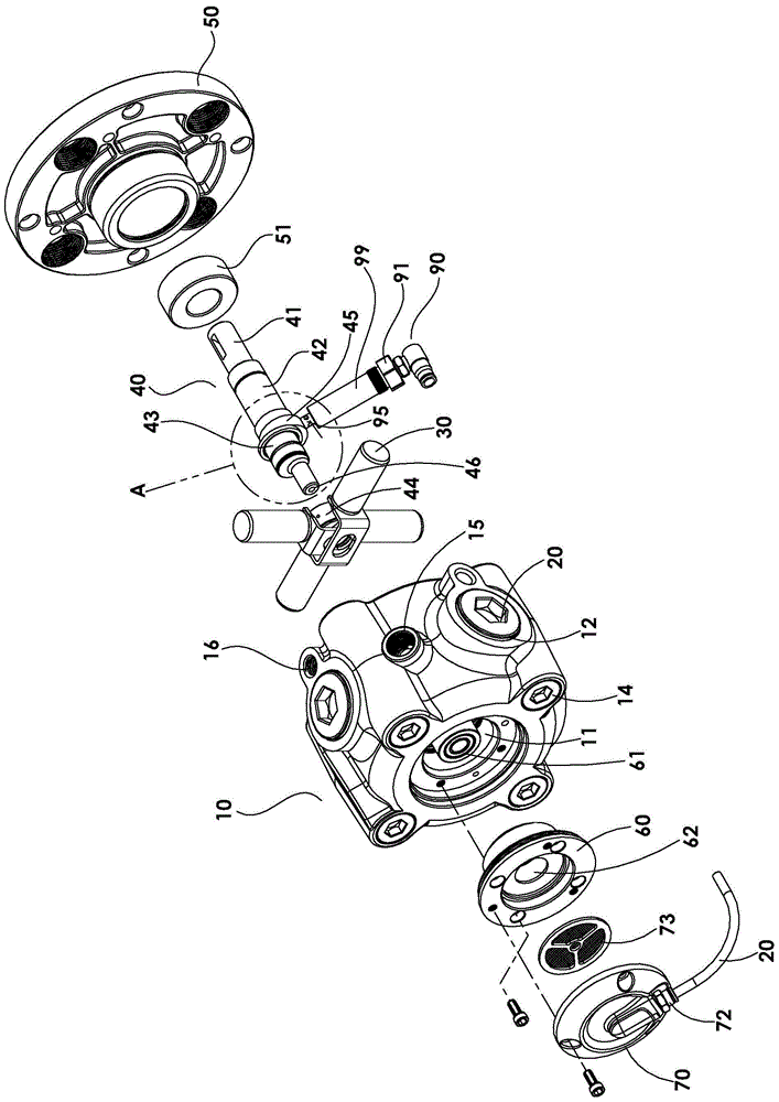
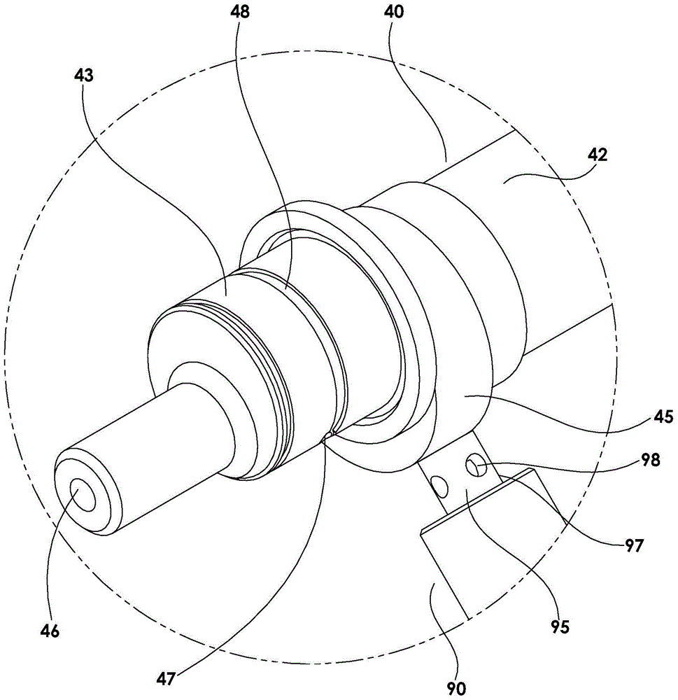
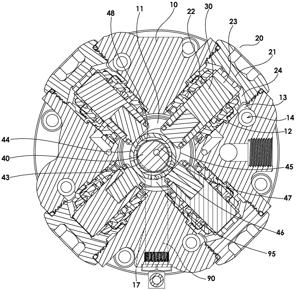
[0036] A liquid pressurized pump output shaft lubrication structure is a pump, such as figure 1 , 2 , 3, 4, 5, including a pump body 10, a plurality of plunger cap groups 20, a plurality of pillar plugs 30 and an output shaft 40; the pump body 10 has a circular core filled with lubricating oil as a mechanical chamber Holes 11, the radial direction of the core hole 11, a plurality of fixed holes 12 are arranged radially and evenly, and each fixed hole 12 is provided with a liquid inlet and outlet 13 in the radial direction, and each of the liquid inlets and outlets 13 is Each is communicated with a non-return valve group 14, and the liquid-inlet non-return end and the liquid-exit non-return end of each of the non-return valve groups 14 are respectively communicated with a liquid-in connection hole 15 and a liquid-out connection hole 16, so that the The liquid inlet and outlet 13 can pass through the liquid inlet check of the check valve group 14, and access the external liquid fr


PUM


Abstract

The invention provides a lubricating structure for an output shaft of a liquid booster pump. A first eccentric part of the output shaft bears the maximum load in the liquid boosting process; a telescopic piston of an oil feeder is directly pushed and pressed by a second eccentric part to act mainly by means of power of the output shaft; lubricating oil in a round core hole is sucked and is pushed, pressed and fed to a deep oil supplying hole in the output shaft; and the lubricating oil is forced to be discharged out of an oil outlet and then is subjected to cyclic supplementation on the surface of the first eccentric part, so that good lubrication is maintained for a long time when a rotating wheel of a contact plunger rotates on the first eccentric part, and the service life of the output shaft or the rotating wheel is effectively prolonged.

Description


Claims


Application Information

Patent Timeline
Owner ZHONGHEYA
Why Eureka
Try Eureka