Metering device for condensate natural gas pipelines facilitating use of turbine flowmeter
A technology of turbine flowmeter and metering device, which is applied in the direction of volume/mass flow, gas fuel, etc. generated by detecting the dynamic effect of fluid flow and mechanical effect, and can solve the problem of inaccurate metering, large impact of oil and gas metering, and unfavorable enterprises. Problems such as management, to achieve the effect of reducing the proportion of liquid phase, simple structure, and strengthening the effect of gas-liquid separation
- Summary
- Abstract
- Description
- Claims
- Application Information
AI Technical Summary
Benefits of technology
Problems solved by technology
Method used
Image

Examples
Embodiment 1
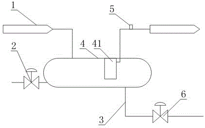
[0019] Such as figure 1 As shown, a condensate natural gas pipeline metering device that is convenient to use a turbine flowmeter includes a fluid pipeline 1 and a metering device 5 arranged on the fluid pipeline 1, and a separation tank 4 is connected in series on the fluid pipeline 1, The separation tank 4 is located at the front end of the metering device 5, and the fluid pipeline 1 on the outlet side of the separation tank 4 is connected to the top or the side of the separation tank 4, and a spiral separator 41 is also arranged in the separation tank 4, and the spiral separation The device 41 is a barrel-shaped structure with an inlet at the lower end, an outlet on the side, and a spiral flow channel between the inlet and the outlet. The fluid pipeline 1 on the outlet side of the separation tank 4 is connected to the outlet of the spiral separator 41. , The separation tank 4 is also provided with a liquid outlet pipe 3, and a shut-off valve 6 is connected in series on the liq
Embodiment 2
[0022] The present embodiment is further limited on the basis of embodiment 1, as figure 1 As shown, the fluid pipeline 1 on the inlet side of the separation tank 4 is connected to the top of the separation tank 4 as a structural form that also reduces the influence of the airflow at the inlet of the separation tank 4 on the condensate.
[0023] In order to facilitate the regular removal of solid impurities in the separation tank 4, the bottom of the separation tank 4 is also provided with a drain pipe 2.
[0024] As a structure convenient for draining the accumulated liquid in the separation tank 4 , the inlet section of the liquid outlet pipe 3 is connected to the bottom of the separation tank 4 .
[0025] As a structural form with simple manufacture and convenient installation, the separation tank 4 is a pressure vessel with elliptical heads at both ends.
PUM
 Abstract
Description
Claims
Application Information
 - R&D Engineer
- R&D Manager
- IP Professional
- Industry Leading Data Capabilities
- Powerful AI technology
- Patent DNA Extraction
Browse by: Latest US Patents, China's latest patents, Technical Efficacy Thesaurus, Application Domain, Technology Topic.
© 2024 PatSnap. All rights reserved.Legal|Privacy policy|Modern Slavery Act Transparency Statement|Sitemap