Multi-knife automatic knife changing type powder laying scraper knife device of 3D printer

A 3D printer and automatic tool change technology, applied in the field of additive manufacturing, can solve the problems of troublesome operation, waste of inert gas, and need to replace blades, so as to reduce production costs and save time.

Inactive Publication Date: 2015-12-23
党金行
View PDF9 Cites 20 Cited by
  • Summary
  • Abstract
  • Description
  • Claims
  • Application Information

AI Technical Summary

Benefits of technology

This patented technology allows for automatic changing of tools used with three-dimensional printing machines without stopping them from moving around during use or requiring maintenance costs associated therewith.

Problems solved by technology

This patented describes three types of machines commonly called 3D printers: metal powders and non metals (PM). These two kinds of material have unique structures and principles due to their specific properties such as size shape, density, porosity, surface chemistry, etc., making them suitable for various applications involving creation of objects through layers on top of each another. However, these technical problem addressed by this patents relates specifically to how well they can perform accurately at high speeds without being affected negatively from factors like temperature changes caused by environmental conditions.

Method used


Image

  • Multi-knife automatic knife changing type powder laying scraper knife device of 3D printer
  • Multi-knife automatic knife changing type powder laying scraper knife device of 3D printer
  • Multi-knife automatic knife changing type powder laying scraper knife device of 3D printer

Examples


Embodiment Construction

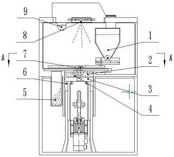
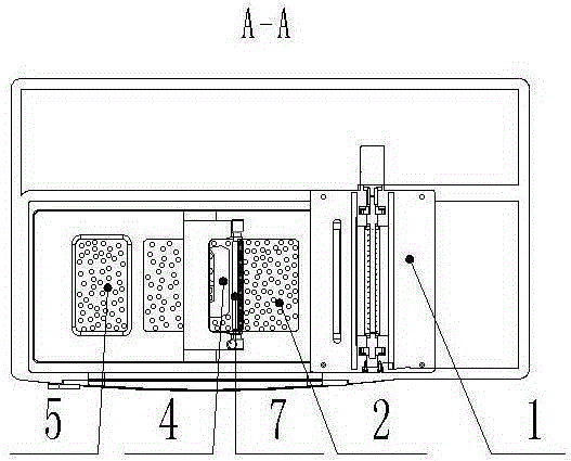
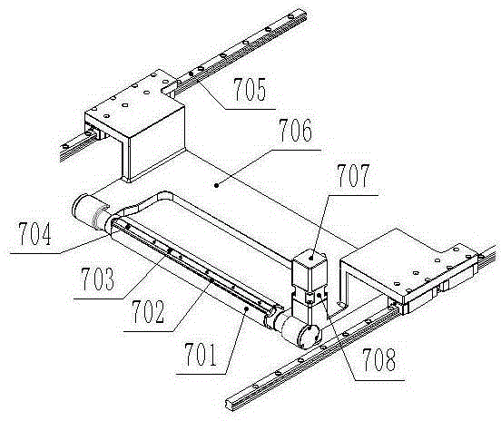
[0013] 1. If image 3 , Image 6 Shown is the embodiment of the powder spreading scraper device. The powder spreading scraper device is placed above the sintered molding or solidified molding surface, can reciprocate along the guide rail (705), and scrape it with its scraper blade (702). Powder, complete the powder spreading process; the powder spreading scraper device is equipped with multiple scraper blades (702), of which the bottom scraper blade is the working blade, and the rest of the blades are spare blades, and the spare blades can be automatically exchanged under the control of the control system to the working position below.

[0014] 2. If Figure 5 , Image 6 As shown, the scraper blade (702) is embedded in the trapezoidal groove of the knife holder shaft (701), and the scraper blade (702) is pressed by the pressing bar (703) and the screw (704). The section of the pressing bar (703) Trapezoidal or wedge-shaped.

[0015] 3. If image 3 , Figure 4 As shown, the


PUM


Abstract

The invention belongs to the field of additive manufacturing, and relates to a multi-knife automatic knife changing type powder laying scraper knife device of a 3D printer. The device is arranged above a sinter molding face or a curing molding face and can do reciprocating motion along guide rails, and scraper knife blades are used for striking off powder and completing the powder laying procedure. The device is characterized in that the scraper knife blades are arranged, the scraper knife blade at the lowest position serves as a work knife blade, the rest of knife blades serve as spare knife blades, the spare knife blades can be automatically exchanged to the lower work positions under control of a control system, and therefore normal running of a machine is guaranteed; shutdown is not needed when a knife holder shaft turns, and therefore the production cost of the 3D printer is reduced, and time is saved.

Description


Claims


Application Information

Patent Timeline
Owner 党金行
Why Eureka
Try Eureka