Material conveying wheel assembly for pneumatic feeding mechanism

A technology of feeding mechanism and feeding wheel, which is applied in the field of mechanical processing, can solve the problems of increasing process difficulty and slow processing efficiency, and achieve the effect of simplifying and compacting the structure and improving work efficiency

Inactive Publication Date: 2016-01-06
CHUZHOU PINZHIDA ELECTRIC TECH
View PDF6 Cites 0 Cited by
  • Summary
  • Abstract
  • Description
  • Claims
  • Application Information

AI Technical Summary

Problems solved by technology

[0002] There is a circular transmission shaft, the two ends of which are provided with symmetrical through-holes that run through the shaft body in the radial direction. The traditional processing method is to use a bench drill to drill one end and then drill the other end. The disadvantage of this processing method is that : First, two processes are required, and second, when processing the other end, in order to make the two holes symmetrical, accurate positioning is required, which greatly increases the difficulty of the process
In addition, there is no automatic feeding and discharging mechanism in the traditional processing method, resulting in slow processing efficiency

Method used


Image

  • Material conveying wheel assembly for pneumatic feeding mechanism
  • Material conveying wheel assembly for pneumatic feeding mechanism
  • Material conveying wheel assembly for pneumatic feeding mechanism

Examples


Example

[0019] (Example 1)

[0020] Figure 1 to Figure 2 A specific embodiment of the present invention is shown.

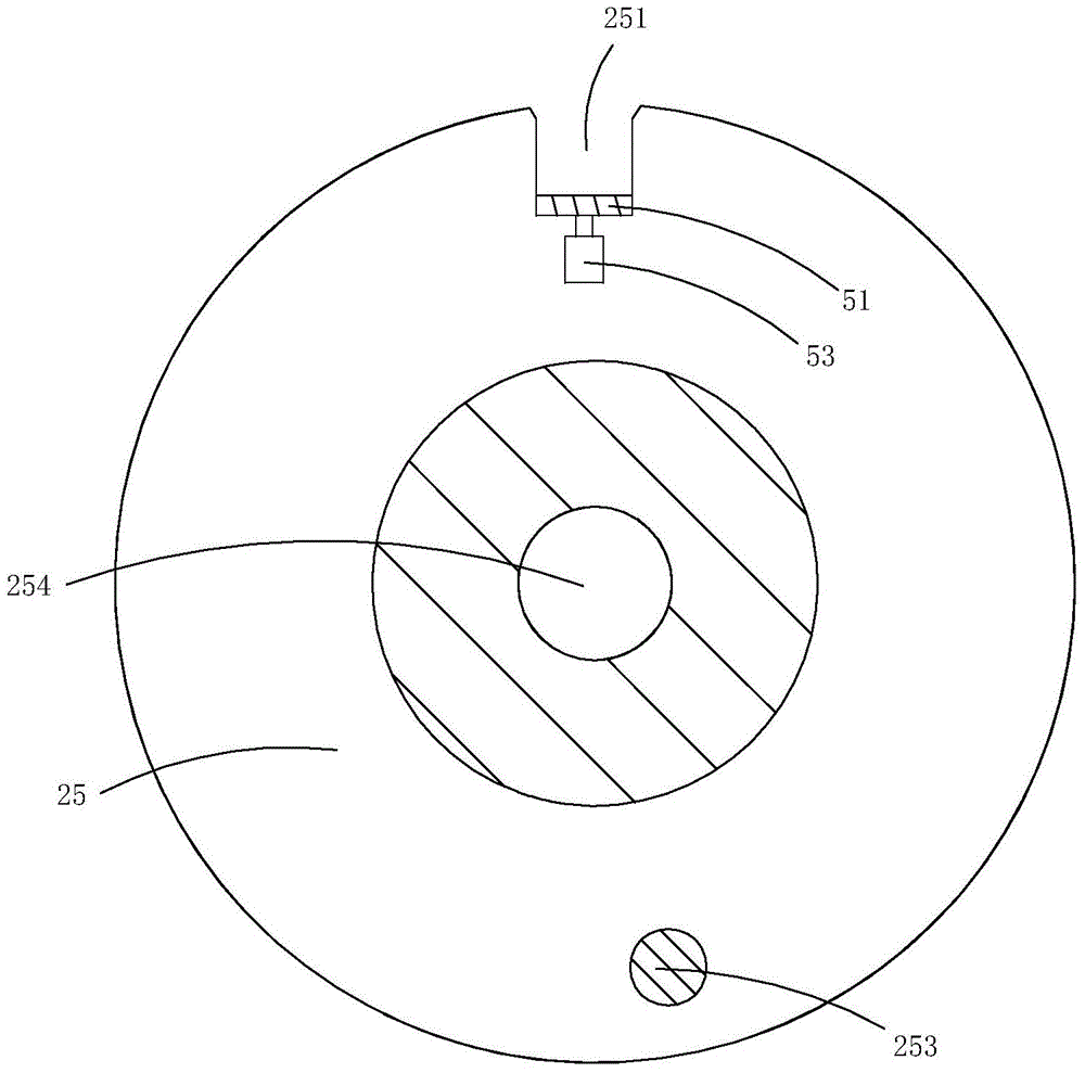
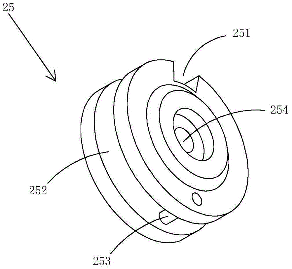
[0021] This embodiment is a transfer wheel assembly used in a pneumatic feeding mechanism, see Figure 1 to Figure 2 As shown, the material transfer wheel assembly includes a material transfer wheel 25 and a clamping cylinder 51 and a push block 52 arranged on the material transfer wheel.

[0022] A trough 251 is provided on the outer peripheral wall of the transfer wheel, and the extension direction of the trough is parallel to the direction of the central axis of rotation of the transfer wheel. The shape of the trough in this embodiment is U-shaped.

[0023] The center of the outer peripheral wall of the transfer wheel is also provided with an annular notch 252 along the circumferential direction, a pin 253 passing through the annular notch, and a central shaft hole 254. The central shaft hole is located at the center of the transfer wheel, and the pin is located outside the cen

Example

[0026] (Application example 1)

[0027] Figure 3 to Figure 12 A specific embodiment of the present invention is shown.

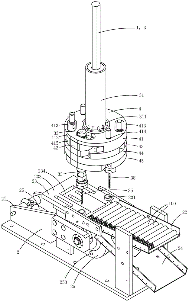
[0028] This embodiment is a pneumatic automatic feed type bench drill, see Figure 3 to Figure 12 As shown, the bench drill includes a bench drill body 1 and a feeding mechanism 2.

[0029] The bench drill body 1 includes a double drill mechanism 3 and a lifting mechanism (not shown in the figure) for driving the double drill mechanism 3 to move up and down.

[0030] The double drill mechanism 3 includes a mounting disk 4, a main shaft 31 rotatably arranged at the center of the mounting disk, a driving wheel 32 fixed on the main shaft, a first transmission shaft 33 rotatably disposed on the mounting disk, and a first transmission shaft fixedly disposed on the upper end of the first transmission shaft. The first driven wheel 34, the first drill bit 35 arranged at the lower end of the first transmission shaft, the second transmission shaft 36 rotatably arranged on the


PUM


Abstract

The invention discloses a material conveying wheel assembly for a pneumatic feeding mechanism. The material conveying wheel assembly comprises a material conveying wheel, a material clamping air cylinder and a pushing block, wherein the material clamping air cylinder and the pushing block are arranged on the material conveying wheel; a material groove is formed in the peripheral wall of the material conveying wheel, and the extending direction of the material groove is parallel to the axial direction of the rotating center of the material conveying wheel; the center of the peripheral wall of the material conveying wheel is further provided with an annular notch, a pin shaft penetrating the annular notch and a center shaft hole in the circumferential direction; and a cylinder body of the material clamping air cylinder is fixedly arranged in the annular notch, and the pushing block is fixedly arranged on a piston of the material clamping air cylinder and located at the bottom of the material groove to serve as the bottom wall of the material groove. Under matching of an external component, automatic material feeding, material claming and material discharging can be achieved, and the structure is relatively simplified and compact; and in addition, as the air cylinder is adopted for executing the motion, compared with traditional electric operation, the working efficiency is obviously improved.

Description


Claims


Application Information

Patent Timeline
Owner CHUZHOU PINZHIDA ELECTRIC TECH
Why Eureka
Try Eureka