Common mode moving circuit for multipoint low voltage differential signal receiver

A low-voltage differential signal, common-mode transfer technology, applied in instruments, electrical digital data processing, etc., can solve the problem of interface restricting high-speed data transmission, and achieve the effect of simplifying circuit design, reducing power consumption, and high system signal-to-noise ratio

Inactive Publication Date: 2016-02-03
INST OF MICROELECTRONICS CHINESE ACAD OF SCI
View PDF2 Cites 8 Cited by
  • Summary
  • Abstract
  • Description
  • Claims
  • Application Information

AI Technical Summary

Benefits of technology

This technology uses an analog component called Error Amplifiers (EA) that detects errors on data transmission lines by comparing them against another set point like ground potential. By controlling this process based upon these differences between two sets points, we can achieve better performance without increasing power usage compared to previous methods such as compressive networks.

Problems solved by technology

This patented technical solution involves improving the performance of electronic devices called interfaces used for transmitting large amounts of digital data over long distances without causing interference or noise issues due to impedance mismatches caused during wired connections.

Method used


Image

  • Common mode moving circuit for multipoint low voltage differential signal receiver
  • Common mode moving circuit for multipoint low voltage differential signal receiver
  • Common mode moving circuit for multipoint low voltage differential signal receiver

Examples


Embodiment Construction

[0020] In order to make the objectives, technical solutions and advantages of the present invention clearer, the embodiments of the present invention will be described in detail below with reference to the accompanying drawings.

[0021] The following describes in detail the embodiments of the present invention, examples of which are illustrated in the accompanying drawings, wherein the same or similar reference numerals refer to the same or similar elements or elements having the same or similar functions throughout. The embodiments described below with reference to the accompanying drawings are exemplary and are only used to explain the present invention, but not to be construed as a limitation of the present invention.

[0022] The following disclosure provides many different embodiments or examples for implementing different structures of the invention. In order to simplify the disclosure of the present invention, the components and arrangements of specific examples are descr


PUM


Abstract

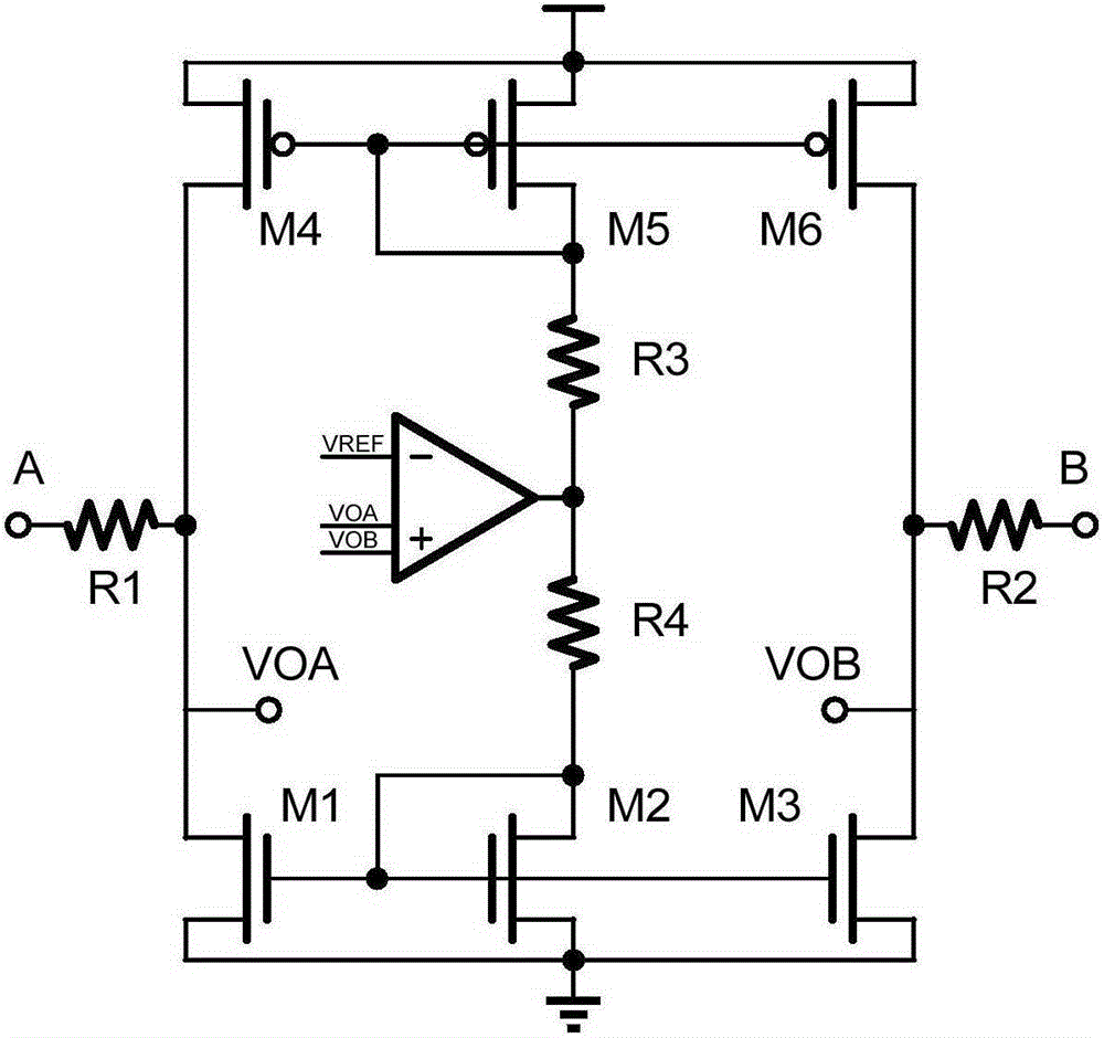
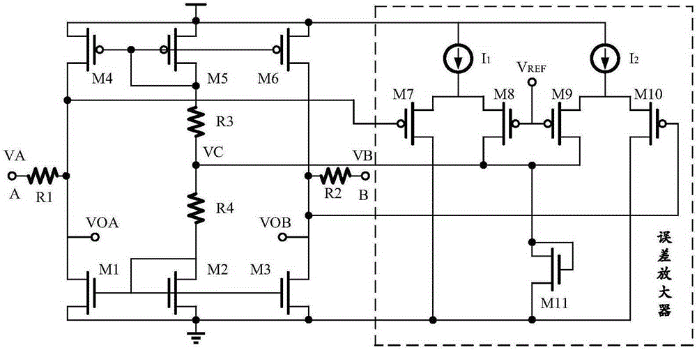
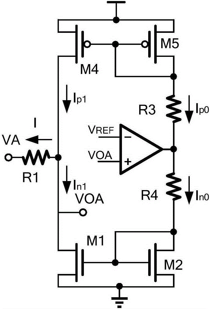
The invention provides a common mode moving circuit for a multipoint low voltage differential signal receiver. The common mode moving circuit comprises a first resistor, a second resistor and a current regulating circuit as well as an error amplifier, wherein the current regulating circuit is formed by a third and fourth resistors and first to sixth transistors; grids of the second and fifth transistors are in a short connection with a drain electrode; grids of the first, second and third transistors are connected with each other and the source ends are grounded; grids of the fourth, fifth and sixth transistors are connected and the source ends are connected with power supply voltage; drain ends of the first and fourth transistors are connected with the first resistance; the third and fourth resistance is in a serial connection between a drain end of the second transistor and a drain end of the fifth transistor; drain ends of the third and sixth transistors are connected with the second resistor; a difference-mode input end of the error amplifier is connected with a reference level; and a common mode input end is connected with the drain ends of the first and third transistors. No effects are caused to input signal differential value; and the common mode moving circuit has system noise ratio higher than a receiver using a compression network.

Description


Claims


Application Information

Patent Timeline
Owner INST OF MICROELECTRONICS CHINESE ACAD OF SCI
Why Eureka
Try Eureka