Adjustable copper pipe bending machine

A bending machine, adjustable technology, applied in the direction of metal processing equipment, feeding device, positioning device, etc., can solve the problems of poor bending effect, cumbersome processing, and inability to bend, so as to save money and reduce human resources , the effect of convenient operation

Inactive Publication Date: 2016-02-10
苏州沃尔非自动化设备有限公司
View PDF7 Cites 3 Cited by
  • Summary
  • Abstract
  • Description
  • Claims
  • Application Information

AI Technical Summary

Benefits of technology

This patented technology provides an improved method or apparatus that helps workers efficiently shape metal materials such as coins into different shapes without having them manually turned over by hand. A pusher system is also included along with another embodiment where two parts (a rotor and a fixed body) work together to make it easier to form complex structures like rings. By moving these components towards each other, they create more precise movements compared to traditional methods involving multiple steps. These improvements improve efficiency and reduce costs associated therewith.

Problems solved by technology

This patented technical problem addressed by this patents relates to improving the flexibility or durability of copper pipings that use them for both industrial applications such as tap waters and thermal control purposes due to their ability to withstand harsh conditions during operation over time.

Method used


Image

  • Adjustable copper pipe bending machine
  • Adjustable copper pipe bending machine
  • Adjustable copper pipe bending machine

Examples


Embodiment Construction

[0018] Specific embodiments of the present invention will be further described in detail below.

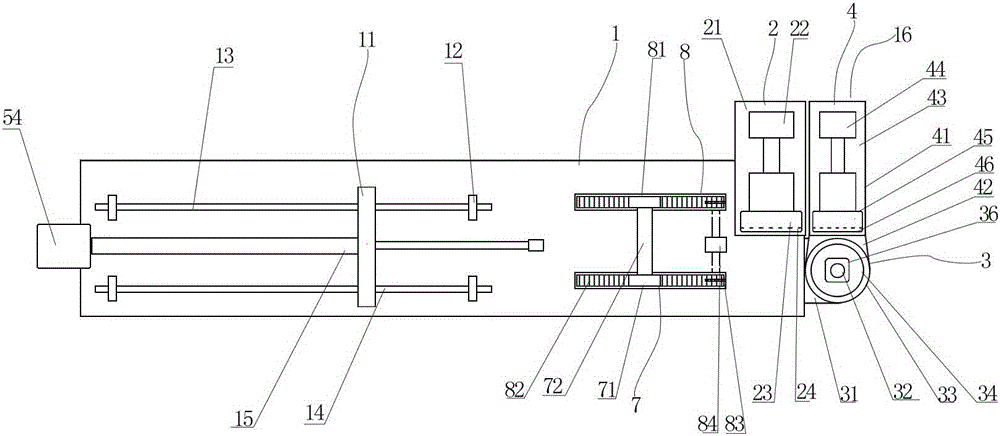
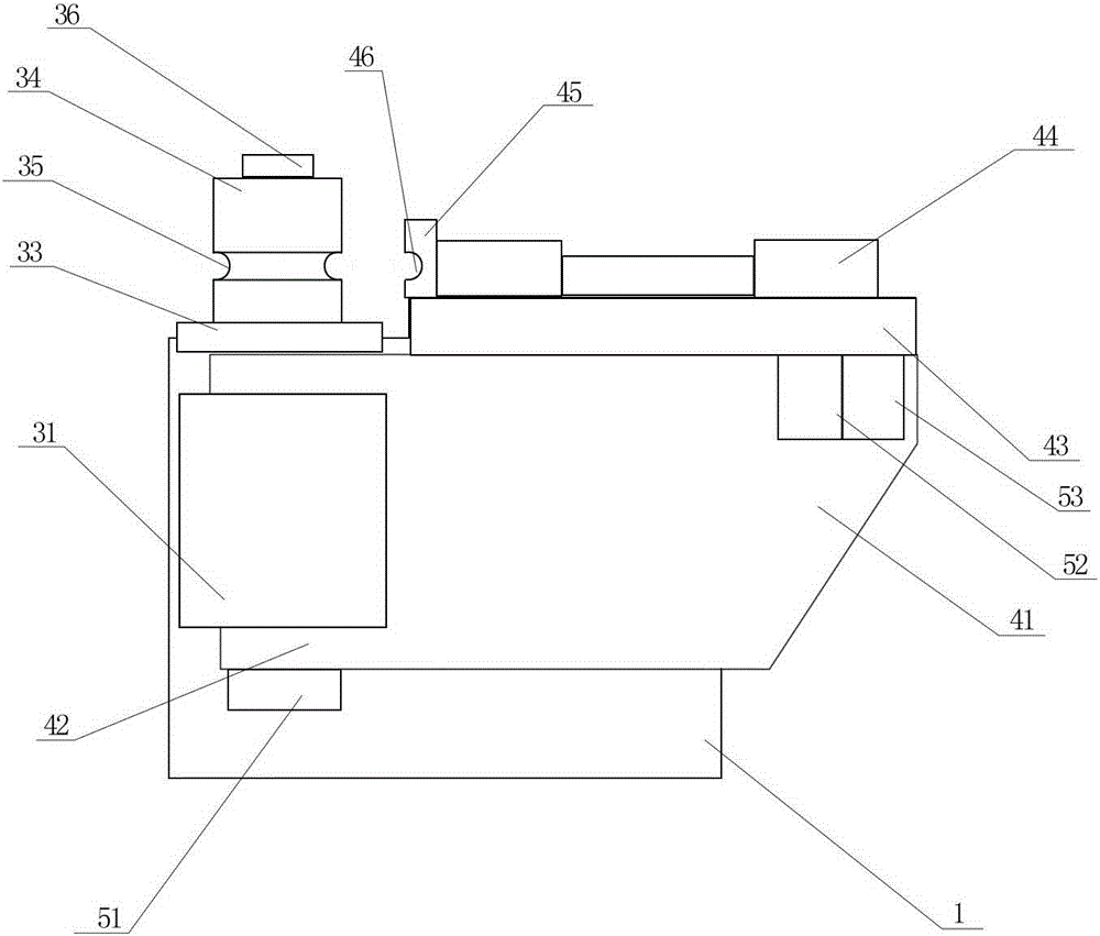
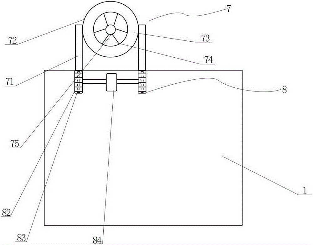
[0019] Such as Figure 1 to Figure 3 As shown, an adjustable copper tube bending machine of the present invention includes a frame 1, and is characterized in that: the frame 1 is provided with a pushing device 11 and a bending device 16 arranged on one side of the pushing device 11, and the folding A rotating mechanism 7 is arranged between the bending device 16 and the pushing device 11. The bending device 16 includes a first bending part 2 arranged on the right side of the top of the frame 1, a rotating part 3 arranged on the right side of the frame 1 and a connection The second bending part 4 of the rotating part 3, the first bending part 2 and the second bending part 4 are arranged in parallel, and the lower part of the rotating mechanism 7 is provided with an adjusting mechanism 8, which includes Two grooves 81, the groove 81 is provided with a rotating toothed belt 82, one sid


PUM


Abstract

The invention discloses an adjustable copper pipe bending machine. The adjustable copper pipe bending machine comprises a rack, and is characterized in that the rack is provided with a pushing device and a bending device disposed on one side of the pushing device; a rotating mechanism is mounted between the bending device and the pushing device; the bending device comprises a first bending part arranged on the right side of the top of the rack, a rotating part disposed on the right side face of the rack and a second bending part connected with the rotating part; the first bending part and the second bending part are arranged in parallel; an adjusting mechanism is disposed under the rotating mechanism and comprises two grooves formed in the top of the rack in parallel; rotating tooth belts are disposed in the grooves; one side of each rotating tooth belt is provided with a gear which is connected with the corresponding rotating tooth belt; the gears are coaxially provided with a third motor; the rotating mechanism comprises two stand columns which are disposed on the two rotating tooth belts respectively; a rotating disc is perpendicularly disposed between the stand columns and comprises a mounting part on an outer ring and a rotating part on an inner ring, and a through hole where a copper pipe passes is formed in the center of the rotating part.

Description


Claims


Application Information

Patent Timeline
Owner 苏州沃尔非自动化设备有限公司
Why Eureka
Try Eureka