Lubricating oil filtering system for turbine body

A technology for steam turbines and lubricating oil, applied in mechanical equipment, engine components, machines/engines, etc., can solve the problems of temporary pipeline material and installation costs, low lubricating oil circulation rate, etc., to increase the circulation flushing rate and reduce the circulation flushing. The effect of time and oil filtering speed

Inactive Publication Date: 2016-02-10
CHINA ENERGY ENG GRP TIANJIN ELECTRIC POWER CONSTR CO LTD
View PDF5 Cites 4 Cited by
  • Summary
  • Abstract
  • Description
  • Claims
  • Application Information

AI Technical Summary

Benefits of technology

This patented technology helps save energy by reducing electrical usage during engine maintenance operations while also improving efficiency. It includes installing a special device called an “flushing filter” that connects two parts - one part goes through with lubricating oils from another location (oil tank) on top or inside other bearings). A small motor-driven hydraulic pump powers up these fluids for quick cleaning without having them stop working altogether. Overall, this design allows for efficient operation at reduced costs compared to traditional methods like manual drainage systems used before they have been restored.

Problems solved by technology

The technical problem addressed in this patented text relates to turbines that use high pressure systems with long pipe lines due to their size and costly maintenance requirements. This makes it difficult or expensive to install these types of systems without sacrificing efficiency.

Method used


Image

  • Lubricating oil filtering system for turbine body

Examples


Embodiment Construction

[0010] The present invention will be further described below in conjunction with the accompanying drawings and embodiments.

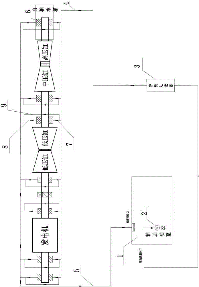
[0011] The lubricating oil filter system of the steam turbine body includes the oil tank 1 and the oil inlet pipe 4 and the oil return pipe 5 connected between the oil tank 1 and the bearings of the steam turbine. The oil tank 1 is equipped with an auxiliary oil pump 2, and the oil tank 1 and the oil inlet pipes of each bearing 4 is provided with a flushing filter 3, the flushing filter 3 is provided with a filter element, and each bearing has a bearing bush 6, and each bearing bush 6 is provided with each bearing bush oil inlet pipe 7 and each bearing bush oil return pipe 8, and each bearing bush oil inlet The pipeline 7 and the oil return pipeline 8 of each bearing pad are short-circuited into the temporary pipeline 9 .

[0012] When the oil filtering system is running, the auxiliary oil pump 2 is started, and the turbine oil enters the system pipeline t


PUM


Abstract

The invention provides a novel lubricating oil filtering system for a turbine body. The lubricating oil filtering system comprises an oil tank, oil inlet pipelines and oil return pipelines, wherein the oil inlet pipelines and the oil return pipelines are connected between the oil tank and bearings of a turbine. An auxiliary oil pump is arranged in the oil tank, washing filters are arranged between the oil tank and the oil inlet pipelines of the bearings, filter elements are arranged in the washing filters, bearing bushes are arranged in the bearings, bearing bush oil inlet pipelines and bearing bush oil return pipelines are arranged on the two sides of the bearing bushes, and temporary pipelines are connected between the bearing bush oil inlet pipelines and the bearing bush oil return pipelines in a short-connection mode. According to the novel lubricating oil filtering system, the washing filters are arranged between the oil tank and the oil inlet pipelines of the bearings, the auxiliary oil pump of the turbine serves as an oil washing power device, the maximum flow requirement of the system is met, the recycle washing multiplying power is increased, and the oil filtering speed is high. By using the system, the electricity consumption can be reduced, the installation work amount of the temporary pipelines can be reduced, an oil filtering pipeline can be shortened, and the recycle washing time of a turbine oil system can be shortened.

Description


Claims


Application Information

Patent Timeline
Owner CHINA ENERGY ENG GRP TIANJIN ELECTRIC POWER CONSTR CO LTD
Why Eureka
Try Eureka