Turbine blade with step gap cooling structure on pressure surface

A technology of cooling structure and turbine guide vanes, applied in stators, engine components, machines/engines, etc., can solve the problems of decreased cooling effect of cold air, cooling and gas mixing, etc., to achieve simple and convenient maintenance process, reduction of aerodynamic losses, manufacturing The effect of reducing the difficulty of the process

Inactive Publication Date: 2016-05-04
BEIHANG UNIV +1
View PDF4 Cites 2 Cited by
  • Summary
  • Abstract
  • Description
  • Claims
  • Application Information

AI Technical Summary

Problems solved by technology

Since the existing air film holes need to flow out from the cold air cavity through the cooling holes on the wall surface to the outside of the high temperature wall surface, they must pass through holes of a certain diameter on the high temperature wall surface, which means that the u

Method used


Image

  • Turbine blade with step gap cooling structure on pressure surface
  • Turbine blade with step gap cooling structure on pressure surface
  • Turbine blade with step gap cooling structure on pressure surface

Examples


Embodiment Construction

[0012] The present invention will be further described in detail below in conjunction with the accompanying drawings.

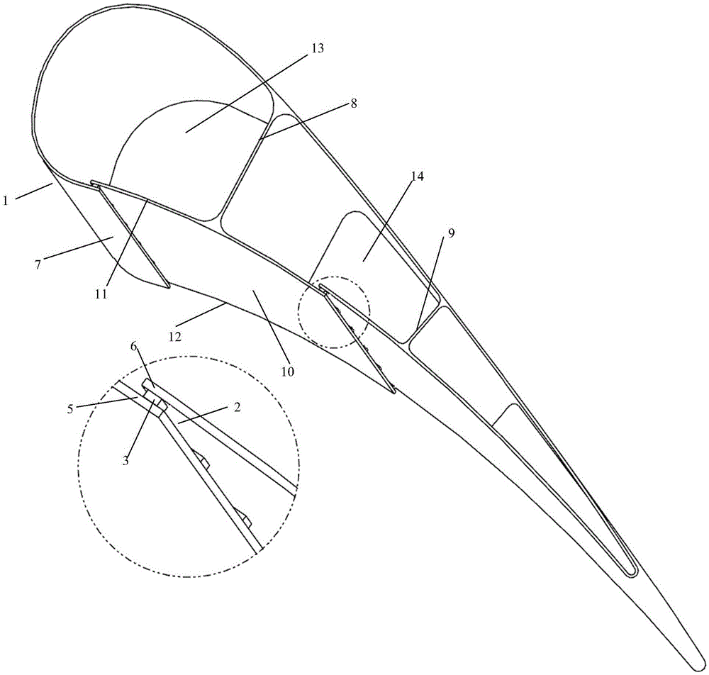
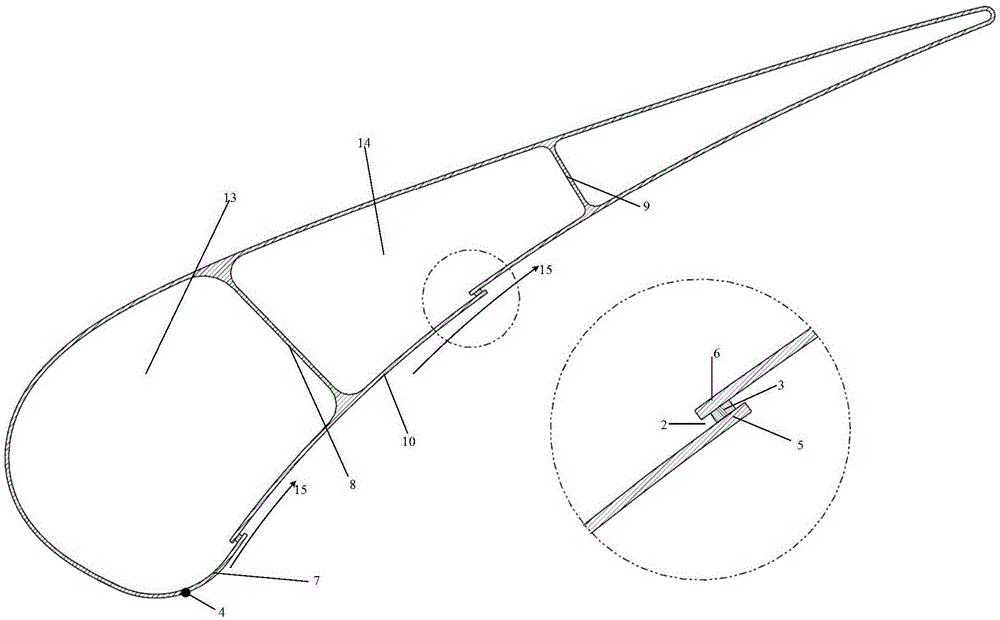
[0013] refer to figure 1 , 2 As shown, the present invention is a novel film cooling structure suitable for a turbine guide vane of a gas turbine engine. The biggest feature of this new film cooling structure is that it adopts a stepped slot-out cooling structure to replace conventional film cooling holes. The stepped slot outflow structure is composed of the outer sheet (5) and the inner sheet (6) located in the blade base (1), and the outer sheet (5) and the inner sheet (6) form a shape on the surface of the blade. Stepped aerodynamic shape. The stepped slot structure can be arranged on the leading edge section (7) and the middle section (10) of the pressure surface of the turbine blade. In the outlet slot (2) of the cooling structure, 3 to 10 connecting ribs (3) can be arranged at the height of the blade between the outer sheet (5) and the inner sheet (6)


PUM


Abstract

The invention discloses a novel gas air film cooling structure for an aircraft engine and a turbine guide blade of a gas turbine. The cooling structure comprises a blade basal body, an air film gap, a connecting rib and a step surface, and is characterized in that a step-shaped gap air film flow outlet structure is formed by an inner blade and an outer blade on the blade pressure surface basal body and the connecting rib, so that cooling air flows out in the tangential direction of the blade surface. The cooling flow outlet structure of a novel blade can form a uniform and consistent cooling air film on the blade surface; the air outlet air film is higher in stability; the vortex effect of cold air flowing out is weakened; the cooling air film is large in covering area and high in cooling efficiency; and meanwhile, the cooling air in the tangential direction is mixed with a high-temperature main flow, so that the pneumatic loss of the blade is reduced, and the blade has both high cooling efficiency and high-efficiency pneumatic performance. The structure also can enable the blade to be produced by a piece connecting structure, and can simplify the blade processing and maintenance process.

Description


Claims


Application Information

Patent Timeline
Owner BEIHANG UNIV
Why Eureka
Try Eureka