Radiator of large bus

A technology for radiators and passenger cars, which is applied in the direction of machines/engines, engine cooling, engine components, etc. It can solve the problems of limited contact area between the cooling plate and the air, inconvenient maintenance and replacement of cooling pipes, and inconvenient heating of the engine, so as to facilitate disassembly , prevent pollution, expand the effect of the area

Inactive Publication Date: 2016-05-04
TIANJIN QINGPU RADIATOR TECH CO LTD
View PDF0 Cites 3 Cited by
  • Summary
  • Abstract
  • Description
  • Claims
  • Application Information

AI Technical Summary

Benefits of technology

This innovation improves upon existing fans by adding an external mountable structure near where they connect to the vehicle's coolant system (radiators). By increasing their distance away from the hot part of the system, there can be more space available within them without being affected negatively affecting its performance or requiring frequent repairs. Additionally, this new technology allows for easy location and removal of the components when needed while maintaining proper functioning. Overall, these improvements improve efficiency and effectiveness over previous designs.

Problems solved by technology

This patented describes how current methods used by older generations of vehicles have limitations with regards to improving their ability to efficiently remove excessive amounts of heat from these systems due to insufficient space available on either one or both sides of the vehicle's body. Additionally, some previous solutions were difficult to install because they had issues with connecting pipes and other parts during maintenance work.

Method used


Image

  • Radiator of large bus
  • Radiator of large bus
  • Radiator of large bus

Examples


Embodiment 1

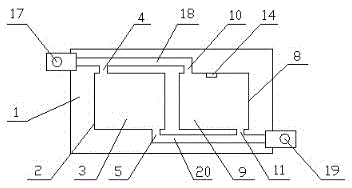
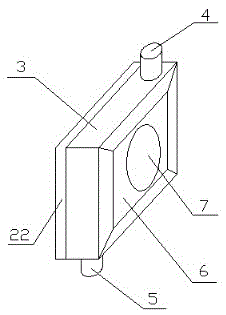
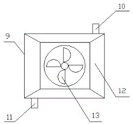
[0013] The upper water port 17 and the lower water port 19 are installed on both sides of the heat dissipation box body 1, and the first water chamber assembly 2 and the second water chamber assembly 8 are installed in the heat dissipation box body 1. The first water chamber assembly 2 includes the first radiator 3, the first water chamber assembly Water inlet 4, first water outlet 5, first windshield 6 and main fan 7, the first water inlet 4 and the first water outlet 5 are respectively installed on both sides of the first radiator 3, the first radiator 3- The side is connected to the first windshield 6, and the main fan 7 is installed on one side of the first windshield 6. The second water chamber assembly 8 includes a second radiator 9, a second water inlet 10, a second water outlet 11, a second Windshield 12, auxiliary fan 13 and temperature sensing device 14, the second water inlet part 10 and the second water outlet part 11 are respectively installed on the two sides of the

Embodiment 2

[0015] During use, the coolant flows into the upper water pipe 18 through the upper nozzle 17, and then enters the first radiator 3 and the second radiator 9 through the first water inlet 4 and the second water inlet 10 respectively, and then flows from the cooling pipe 15 respectively The first water outlet part 5 and the second water outlet part 11 flow out and enter the water outlet 19 through the downpipe 20. When the radiator is working, the temperature sensing device 14 monitors the internal temperature of the second radiator 9. When the temperature is higher than the set value, The controller 21 receives the signal and starts the auxiliary fan 13 to assist in heat dissipation, and the main fan 7 is always in the working state during the process.


PUM


Abstract

The invention discloses a radiator of a large bus. The radiator is characterized in that the radiator comprises a radiating box body, a first water chamber component, a second water chamber component, a radiating pipe, a mounting clamping groove, an upper water port, an upper water pipe, a lower water port, a lower water pipe, a controller and a silt baffle plate, wherein the upper water port and the lower water port are formed in the two sides of the radiating box body; the first water chamber component and the second water chamber component are mounted in the radiating box body; and the first water chamber component comprises a first radiator part, a first water feeding part, a first water discharge part, a first wind protection window and a main fan. The fan is mounted at inner side, instead of the outer side, so that circulation of an air flow is improved; the baffle plate is additionally adopted, so that pollution to a heating panel by silt is avoided; with the additional design of the mounting clamping groove, the technical requirement on a worker is reduced, and the radiator is more convenient to dismount during maintenance and repair; and a temperature induction device and the controller control an auxiliary fan, so that an engine can enter a working state more quickly, and the waste of electric energy can be reduced.

Description


Claims


Application Information

Patent Timeline
Owner TIANJIN QINGPU RADIATOR TECH CO LTD
Why Eureka
Try Eureka