Sealing structure and gate valve with sealing structure

A sealing structure and sealing failure technology, applied in shaft sealing, engine sealing, sliding valve and other directions, can solve the problem that the sealing structure cannot meet the continuous sealing and permanent sealing at the same time, and achieve small deformation and small extrusion force. , the effect of long service life

Inactive Publication Date: 2016-06-01
NEWAY VALVE SUZHOU
View PDF14 Cites 5 Cited by
  • Summary
  • Abstract
  • Description
  • Claims
  • Application Information

AI Technical Summary

Benefits of technology

This patented design allows for better fluid tightening while maintaining reliable operation even if there may occur leaks or failures during use. It achieves these technical benefits without requiring multiple components like separate parts such as an oil tank and a resin container. Additionally, the system uses three different types of materials - primary and secondary seals, each containing two layers of rubber instead of just single layer but allowing flexibility in selecting the type of material based upon their respective functions. Overall, this technology provides improved reliance and efficiency over existing designs.

Problems solved by technology

This patented technical problem addressed by this patents relates to improving the performance and durability of under water gate valve systems that include underground gate valvices due to their complicated design and long lifetimes caused by repeated replacements or poor maintenance.

Method used


Image

  • Sealing structure and gate valve with sealing structure
  • Sealing structure and gate valve with sealing structure
  • Sealing structure and gate valve with sealing structure

Examples


Embodiment 1

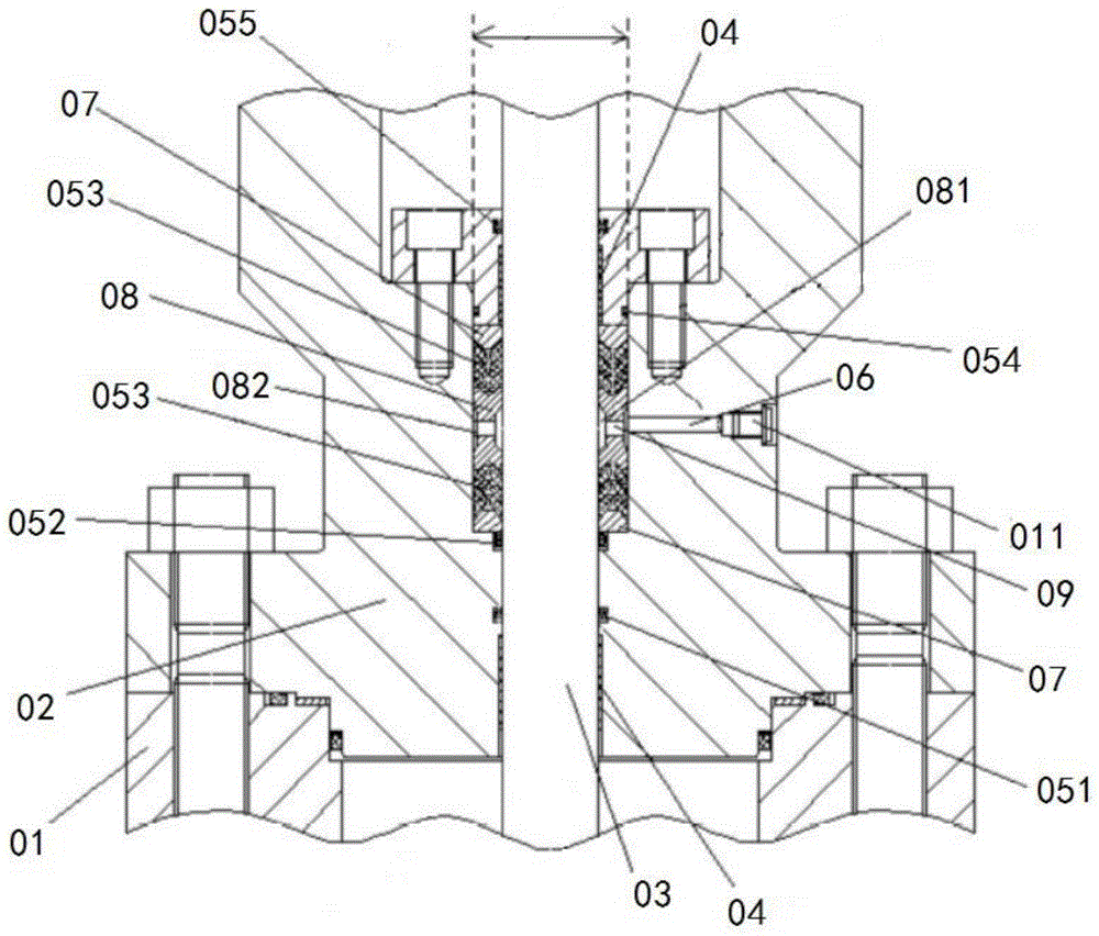
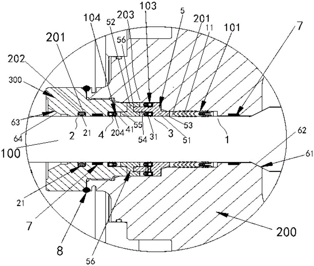
[0051] This embodiment provides a sealing structure, which is suitable for being arranged between the valve stem 100 and the valve cover 200 sleeved on the valve stem 100, refer to Figure 2-3 shown, including:

[0052] The first seal 1 is used to seal one end of the valve stem 100;

[0053] The second seal 2 is used to seal the other end of the valve stem 100;

[0054] The third seal 3 is arranged between the first seal 1 and the second seal 2, and close to the first seal 1, and replaces the first seal only when the seal of the first seal 1 fails 1 to act as a seal;

[0055] The fourth seal 4 is arranged between the first seal 1 and the second seal 2 and close to the second seal 2, and only replaces the second seal when the seal of the second seal 2 fails 2 play a sealing role.

[0056] In the sealing structure in this embodiment, a first seal 1 and a second seal 2 are respectively provided at both ends of the valve stem 100, and at least one third seal 3 and at least one th

Embodiment 2

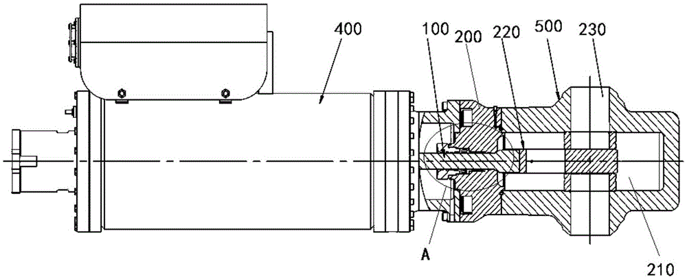
[0086] This embodiment provides a gate valve, including:

[0087] The driving mechanism 400 has an output shaft;

[0088] The valve body 500 has an inner cavity 210, the inner cavity 210 has a gate 220 inside, and a pipe 230 that can be opened or sealed closed by the gate 220;

[0089] The valve stem 100 is fixedly connected to the output shaft at one end, and fixedly connected to the gate plate 220 at the other end, so as to drive the gate plate 220 to move under the drive of the driving mechanism 400, thereby driving the gate plate 220 to open or close said conduit 230;

[0090] The valve cover 200 is sleeved on the outside of the valve stem 100 and fixedly connected to the valve body 500 and the driving mechanism 400;

[0091] A sealing structure as described in Embodiment 1 is also provided between the valve cover 200 and the valve stem 100 .

[0092] The gate valve of this embodiment has the sealing structure described in Embodiment 1, and therefore has the advantages bro


PUM


Abstract

The invention provides a sealing structure and a gate valve with the sealing structure. The sealing structure is suitable for being arranged between a valve rod and a valve deck, wherein the valve deck is arranged on the valve rod in a sleeving manner. The sealing structure comprises a first seal, a second seal, at least one third seal and at least one fourth seal. The first seal is used for sealing one end of the valve rod. The second seal is used for sealing the other end of the valve rod. The third seals are arranged between the first seal and the second seal, are close to the first seal and can replace the first seal to achieve the sealing function only when sealing of the first seal fails. The fourth seals are arranged between the first seal and the second seal, are close to the second seal and can replace the second seal to achieve the sealing function only when sealing of the second seal fails. Due to the fact that the third seals and the fourth seals are arranged, the sealing structure can achieve continuous sealing, and a good sealing effect can be guaranteed. In addition, when the first seal and the second seal carry out seal normally, the third seals and the fourth seals do not bear liquid pressure, deformation is small, extrusion force between the sealing structure and the valve rod is small, abrasion is small, and the service life is long.

Description


Claims


Application Information

Patent Timeline
Owner NEWAY VALVE SUZHOU
Why Eureka
Try Eureka