Chain transmission mechanism for grinding machine

A chain drive, grinding machine technology, applied in the direction of transmission, grinding drive, grinding machine parts, etc., can solve the problems of motor and reducer damage, low grinding accuracy, low efficiency, etc., to reduce vibration and improve grinding. Accuracy and grinding efficiency, vibration mitigation effect

Inactive Publication Date: 2016-06-08
芜湖中驰机器人科技有限公司
View PDF6 Cites 4 Cited by
  • Summary
  • Abstract
  • Description
  • Claims
  • Application Information

AI Technical Summary

Problems solved by technology

[0002] In the field of mechanical processing, a grinding machine is a commonly used processing equipment. During the grinding process, vibration will be generated. Although the commonly used gear transmission mechanism has high transmission efficiency, it cannot alleviate the vibration. The

Method used


Image

  • Chain transmission mechanism for grinding machine
  • Chain transmission mechanism for grinding machine
  • Chain transmission mechanism for grinding machine

Examples


Embodiment Construction

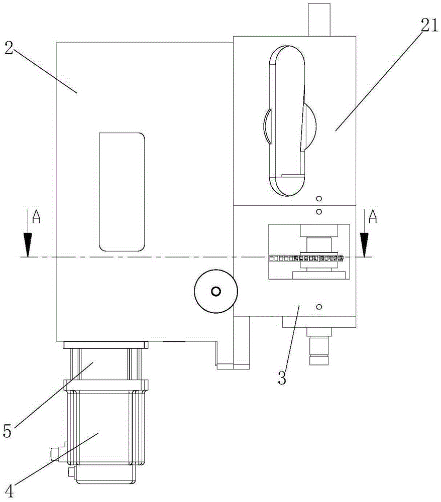
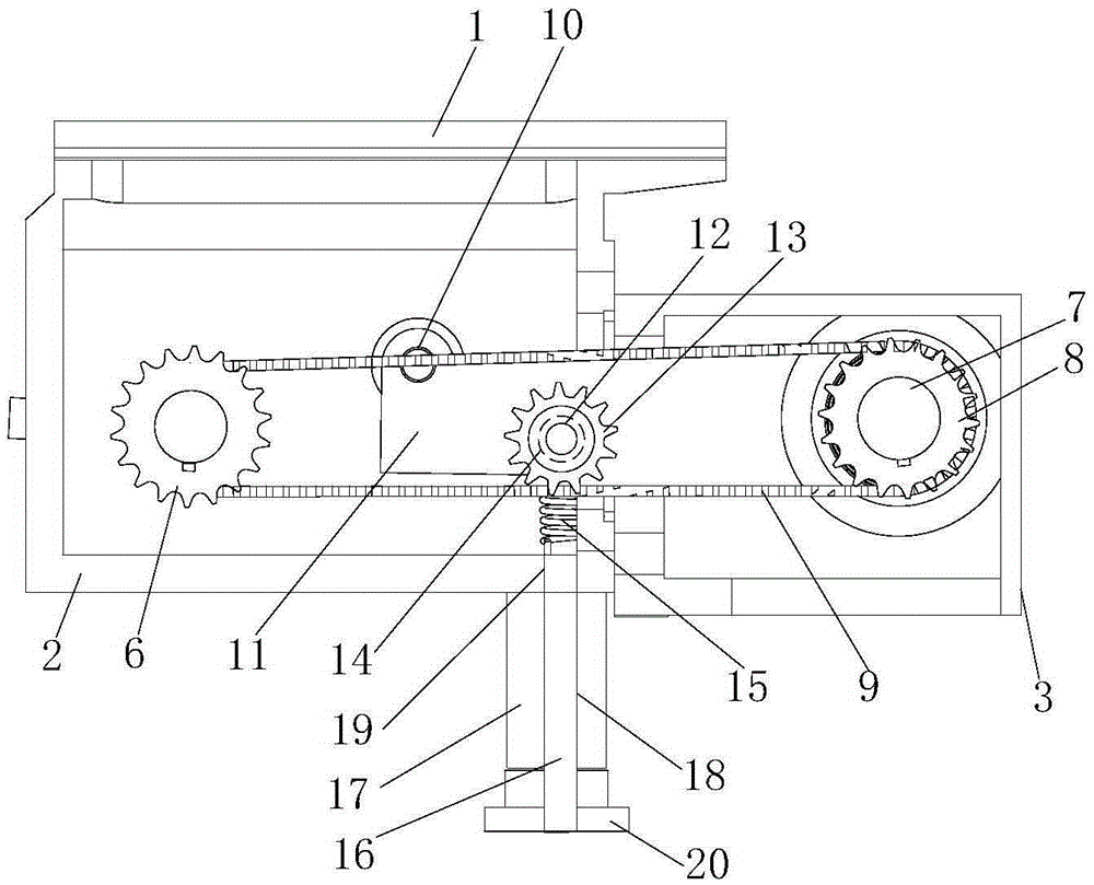
[0019] Such as Figure 1-3 as shown, figure 1 It is a structural schematic diagram of a chain transmission mechanism for a grinding machine proposed by the present invention; figure 2 for figure 1 A-A sectional schematic diagram in ; image 3 It is an axonometric schematic diagram of a chain transmission mechanism for a grinding machine proposed by the present invention.

[0020] refer to Figure 1-3 , a chain transmission mechanism for grinding machines proposed by the present invention, including a bracket 1, a first housing 2, a second housing 3, a motor 4, a reducer 5, a driving sprocket 6, a guide shaft 7, and a driven sprocket 8 and chain9;

[0021] The first housing 2 is fixed on the bracket 1, and a slide groove 10 is provided under the bracket 1 for fixed connection with the grinding machine, so as to facilitate reasonable adjustment of the relative position with the grinding machine, thereby improving the accuracy and applicability of grinding.

[0022] The motor


PUM


Abstract

The invention proposes a chain transmission mechanism for a grinding machine. The mechanism comprises a bracket, a first shell, a second shell, a motor, a speed reducer, a driving chain wheel, a guide shaft, a driven chain wheel, a chain and a tension adjusting mechanism; the tension adjusting mechanism includes an adjusting block fixed shaft, an adjusting block, an adjusting chain wheel shaft, an adjusting chain wheel, an adjusting spring fixed piece, an adjusting spring, an adjusting screw rod and an adjusting screw rod fixed base; the adjusting chain wheel is positioned on the inner side of the chain; the adjusting screw rod rotates in the adjusting screw rod fixed base; and the adjusting spring drives the adjusting chain wheel to move to one side of a center connecting line of the driving chain wheel and the driven chain wheel, so that the chain is tensioned, the transmission efficiency and the transmission stability are improved, and the polishing precision and the polishing efficiency of the grinding machine are improved.

Description


Claims


Application Information

Patent Timeline
Owner 芜湖中驰机器人科技有限公司
Why Eureka
Try Eureka