Hydraulic lifting wall brushing machine manually controlled by sprockets and chains

A technology of hydraulic lifting and sprocket chain, applied in construction, building structure and other directions, can solve problems such as cost increase, paint waste, waste of paint and paint, etc., to improve the speed of wall painting, reduce costs, and save paint. Effect

Inactive Publication Date: 2015-05-20
GUANGXI UNIV
View PDF4 Cites 1 Cited by
  • Summary
  • Abstract
  • Description
  • Claims
  • Application Information

AI Technical Summary

Benefits of technology

This patented device has two main technical features: it uses an electric motor that controls its movement through gears instead of traditional methods like cranking wheels; this allows quicker cleanings without wasted material compared to other ways. It achieves these benefits even at larger areas where there are more space than usual on house walls.

Problems solved by technology

This patented technical problem addressed in this patents relates to manually carrying out large amounts of paints during house cleanings with traditional methods like scrubbing or wipers. These techniques can lead to wasted material due to their high labor costs and lack flexibility when trying to reach certain areas without being able to effectively remove any remaining materials from them.

Method used


Image

  • Hydraulic lifting wall brushing machine manually controlled by sprockets and chains
  • Hydraulic lifting wall brushing machine manually controlled by sprockets and chains

Examples


Embodiment Construction

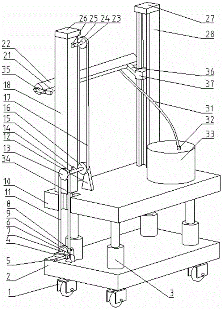
[0014] The lifting wall painting machine of the present invention will be further described below in conjunction with the accompanying drawings.

[0015] Such as figure 1 and figure 2 As shown, two symmetrically arranged left uprights 18 and right uprights 28 are fixed on the second base 10, and the left upright 18 and the right upright 28 are respectively provided with a slidingly fitted left slider 19 and a right slider on the opposite inner sides. 37. The bottom of left column 18 is provided with second drive sprocket 16 and first driven sprocket 13, and second drive sprocket 16 and first driven sprocket 13 are installed on the second axle 14, and second axle 14 passes bearing Installed on the second fixed block 12 and the third fixed block 15, the second fixed block 12 is fixed on the second base 10, the third fixed block 15 is fixed on the left column 18; the top of the left column 18 is provided with a second slave The driven sprocket 23 and the second driven sprocket 2


PUM


Abstract

The invention discloses a hydraulic lifting wall brushing machine manually controlled by sprockets and chains. The hydraulic lifting wall brushing machine comprises a first base, a second base, a paste spraying cylinder and a rolling brush. The paste spraying cylinder is connected with a coating material tank. Stand columns are fixed on the second base. The lower portion of one stand column is provided with a second driving sprocket and a first driven sprocket, wherein the second driving sprocket and the first driven sprocket are arranged coaxially. The upper portion of one stand column is provided with a second driven sprocket. The second driving sprocket is connected with the second driven sprocket through the second chain. One sliding block is fixed on the second chain. The sliding blocks are fixedly connected with the paste spraying cylinder. Connecting rods are fixed on the two ends of the paste spraying cylinder. A rolling brush shaft is fixed between the two connecting rods. The rolling brush shaft is provided with the rolling brush. The first base is arranged below the second base. A hydraulic cylinder is arranged between the first base and the second base. A first driving sprocket is arranged on the first base. The first driving sprocket is connected with the first driven sprocket through a first chain. According to the hydraulic lifting wall brushing machine, the height of the rolling brush is convenient to adjust, the wall brushing speed is increased, coating materials are saved, and the decoration cost is lowered.

Description


Claims


Application Information

Patent Timeline
Owner GUANGXI UNIV
Why Eureka
Try Eureka