Liquid pump type air compressor

A technology of air compressors and liquid pumps, applied in the field of gas compressors, which can solve the problems of easy overheating and damage of compressors, high cost of manufacturing and use, and high cost of silence, and achieve the effects of high compression efficiency, high airtightness, and simple structure

Inactive Publication Date: 2016-06-08
万建雄 +4
View PDF6 Cites 0 Cited by
  • Summary
  • Abstract
  • Description
  • Claims
  • Application Information

AI Technical Summary

Benefits of technology

This patented design allows for more efficient operation by separating different parts within each tank while maintaining an impervious seal between them. It also simplifies construction without requiring extra components like filters or pipes.

Problems solved by technology

Technological Problem: Current air compressers require complicated structures that generate significant noise while operating at very high levels of power consumption due to their complexity. Additionally, current designs often involve multiple components like an electrical motor driving another component called a shaft, causing damage when exposed to excessive temperatures.

Method used


Image

  • Liquid pump type air compressor
  • Liquid pump type air compressor

Examples


Embodiment 1

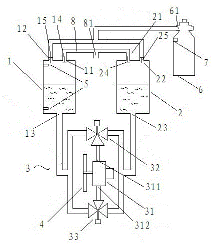
[0024] Such as figure 1 As shown, the liquid pump air compressor provided in this embodiment mainly includes a first compressor tank 1, a second compressor tank 2 and a driving device 3. The first compressed air tank 1 and the second compressed air tank 2 are respectively connected to the driving device 3.

[0025] Specifically, the upper end of the first compressed air tank 1 has a first air inlet 11 and a first air outlet 12, and the lower end has a first liquid infusion port 13. A one-way valve 14 is provided on the first air inlet 11, and a one-way valve 15 is provided on the first air outlet 12, that is, the first air inlet 11 can only take in air but not air out, and the first air outlet 12 can only let out air No air intake. There is no valve on the first infusion port 13, so that the first infusion port 13 can both enter and exit water.

[0026] The upper end of the second compressor tank 2 has a second air inlet 21 and a second air outlet 22, and the lower end has a second

Embodiment 2

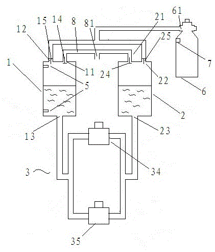
[0037] The difference between the liquid pump air compressor provided in this embodiment and the first embodiment is the structure of the driving device 3.

[0038] Such as figure 2 As shown, the driving device 3 includes a first water pump 34 and a second water pump 35, the first water pump 34 and the second water pump 35 are arranged side by side, the first infusion port 13 of the first compressed air tank 1 and the second infusion of the second compressed air tank 2 The ports 23 are respectively connected to the first water pump 34 and the second water pump 35 through a Y-shaped three-way water pipe. The first water pump 34 is used to squeeze the water in the first compressed air tank 1 into the second compressed air tank 2, and the second water pump 35 It is used to squeeze the water in the second compressor tank 2 into the first compressor tank 2, or the first water pump 34 and the second water pump 35 are driven in opposite directions.

[0039] The function of the driving devi


PUM


Abstract

The invention discloses a liquid pump type air compressor which comprises a first compressed air tank, a second compressed air tank and a driving device, wherein a one-way valve is arranged on a first air inlet of the first compressed air tank; another one-way valve is arranged on a first air outlet of the first compressed air tank; another one-way valve is arranged on a second air inlet of the second compressed air tank; another one-way valve is arranged on a second air outlet of the second compressed air tank; a first liquid inlet of the first compressed air tank and a second liquid inlet of the second compressed air tank are respectively connected with the driving device. As two compressed air tanks are provided, and the air inlets and the air outlets of the two compressed air tanks are provided with one-way valves, the driving device is enabled to repeatedly extrude liquids in the two compressed air tanks, and then air in the two compressed air tanks can be alternatively compressed; as the liquids for compression are always in sealed environments, a circulation system can be formed, and the compressor is good in sealing property and high in compression efficiency; moreover due to formation of the circulation system of the two compressed air tanks, other water storage equipment is not needed, and thus the compressor can be relatively simple in structure; as water can be used as a compression medium, clean compressed air can be produced.

Description


Claims


Application Information

Patent Timeline
Owner 万建雄
Why Eureka
Try Eureka