Electric central frame for crankshaft

A center frame and crankshaft technology, applied in the field of crankshaft electric center frame, can solve the problems of poor center positioning performance of lathe fixtures, many operation steps, time-consuming and laborious, and achieve fast positioning speed, high positioning accuracy, and improve work efficiency and machining accuracy. Effect

Active Publication Date: 2016-08-24
SICHUAN FEIYA AUTO PARTS CO LTD
View PDF12 Cites 3 Cited by
  • Summary
  • Abstract
  • Description
  • Claims
  • Application Information

AI Technical Summary

Problems solved by technology

In the process of machining the big and small shaft heads and the main shaft hole of the crankshaft on the lathe, it is necessary to support and center the two ends of the crankshaft. The current lathe fixture has the following problems: the lathe fixture

Method used


Image

  • Electric central frame for crankshaft
  • Electric central frame for crankshaft

Examples


Embodiment Construction

[0015] The present invention will be further described below in conjunction with accompanying drawing:

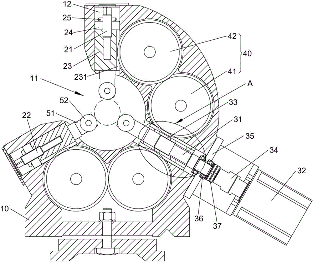
[0016] refer to figure 1 with figure 2 , the present invention provides a crankshaft electric center frame, comprising a base 10, on which a transmission shaft 1 21, a transmission shaft 2 22 and a transmission shaft 3 31 are arranged, the transmission shaft 1 21, the transmission shaft 22 and the transmission shaft 3 31 The three are mutually distributed in a 120° ring shape, so that the force is stable and the clamping is reliable. Transmission shaft one 21 is positioned at the base 10 upper end, and transmission shaft two 22 and transmission shaft three 31 are symmetrically arranged below transmission shaft one 21, and the base 10 between transmission shaft one 21 and transmission shaft two 22 is provided with for placing the crankshaft. The opening groove 11. A driven rack sleeve 23 is fixedly connected to the first transmission shaft 21 and the second transmission sha


PUM


Abstract

The invention discloses an electric central frame for a crankshaft. The electric central frame comprises a base, wherein a transmission shaft I, a transmission shaft II and a transmission shaft III are arranged on the base; driven rack sleeves are fixedly connected on the transmission shaft I and the transmission shaft II; driven rack parts are arranged on the driven rack sleeves; a motor is arranged at one end of the transmission shaft III; a drive rack sleeve is arranged at the other end of the transmission shaft III; a thread transmission part is arranged on the transmission shaft III; a thread transmission hole is formed in the drive rack sleeve; the thread transmission part is arranged in the thread transmission hole; a pair of drive rack parts are symmetrically arranged on the drive rack sleeve; and gear transmission pairs are arranged between the drive rack parts and the driven rack parts. According to the electric central frame for the crankshaft, the drive rack parts transmit power to the driven rack sleeves through the gear transmission pairs, so that large and small shaft heads of the crankshaft are clamped and released through three locating bearings, the locating speed is high, and the locating accuracy is high.

Description


Claims


Application Information

Patent Timeline
Owner SICHUAN FEIYA AUTO PARTS CO LTD
Why Eureka
Try Eureka