Drilling pump used for drilling

A drilling pump and drilling technology, which is applied in the direction of pumps, piston pumps, liquid displacement machinery, etc., can solve the problems of more restrictions in the production process, cumbersome overall layout, and long production cycle, and achieve simplified power transmission system and simplified structure , The effect of reducing production costs

Inactive Publication Date: 2015-03-25
闫晖
View PDF0 Cites 0 Cited by
  • Summary
  • Abstract
  • Description
  • Claims
  • Application Information

AI Technical Summary

Benefits of technology

This technology reduces the size, complexity, and mass of an engine's power train by replacing it entirely from its pistons or rings that are connected directly onto one another instead through their bearings. It also simplifies the design for each component without requiring any extra parts like bolts or welding. Overall, this makes manufacturing processes more efficient while minimizing costs associated therewith.

Problems solved by technology

In this patented technical problem addressed by the inventor describes how current methods for controlling the movement of drills are complex and require many components that take up space on both sides of the machine's housing.

Method used


Image

  • Drilling pump used for drilling
  • Drilling pump used for drilling
  • Drilling pump used for drilling

Examples


Embodiment 1

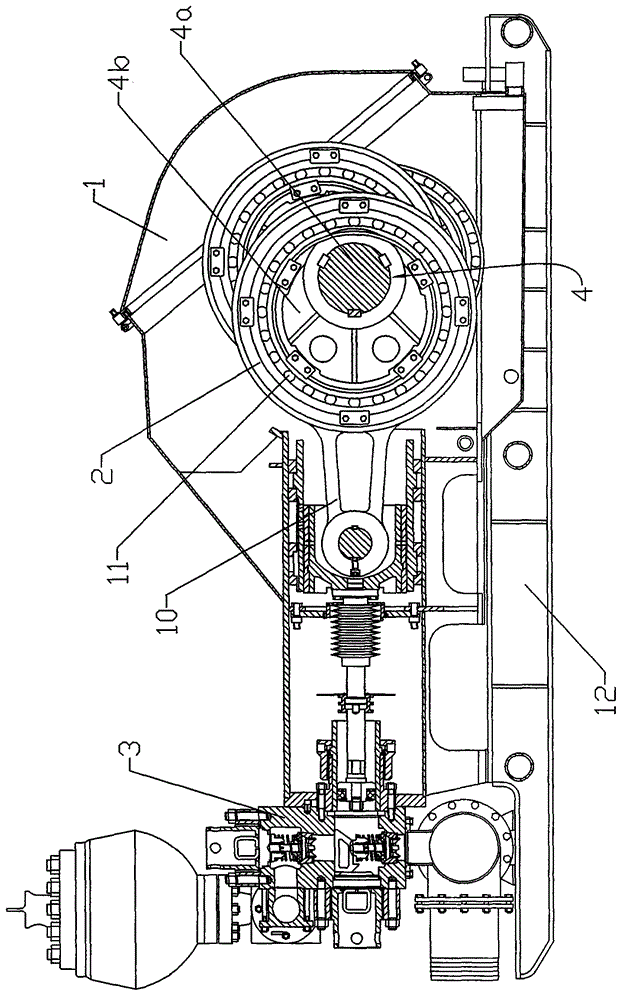
[0015] Example 1, such as figure 1 , figure 2 As shown, a drilling pump for drilling includes a pump body and a power unit, the pump body is fixed on the base 12, the pump body includes a frame assembly 1, a power end assembly 2 and a hydraulic end assembly 3, and the power end assembly Cheng 2 has an eccentric shaft 4, and the power input end of the eccentric shaft 4 is directly connected with the power output end of the power device.

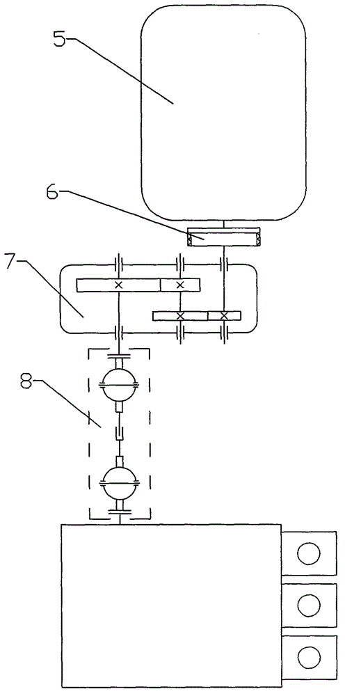
[0016] Such as figure 2 As shown, the power device includes a power source 5, a speed reducer 7, a clutch 6 and a cardan shaft 8, a clutch 6 is connected between the power source 5 and the clutch input end, a cardan shaft 8 is connected to the output end of the clutch 7, and the speed reducer 7 It is a two-stage transmission gearbox.

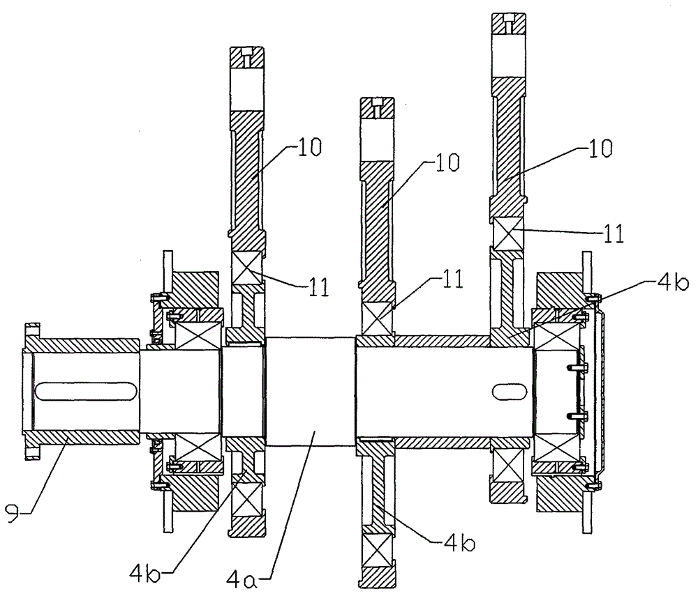
[0017] Such as image 3 As shown, the eccentric shaft 4 is composed of a stepped shaft 4a and three eccentric blocks 4b fixedly connected with the stepped shaft 4a. The power input end of the eccentric shaft

Embodiment 2

[0019] In Embodiment 2, the eccentric shaft 4 of the drilling pump is an integral structure with three bell cranks obtained by forging, and the other structures of the drilling pump are the same as in Embodiment 1.


PUM


Abstract

The invention relates to a drilling pump used for drilling. The drilling pump comprises a pump body and a power plant. The pump body comprises a rack assembly, a power end assembly and a fluid end assembly. The power end assembly is provided with an eccentric shaft, and the power input end of the eccentric shaft is directly connected with the power output end of the power device. The power device comprises a power source, a speed reducer, a clutch and a universal shaft. The clutch is connected between the power source and the input end of the clutch, and the output end of the clutch is connected with the universal shaft. As a pinion shaft and a gear ring which is fixed to a crankshaft and meshed with the pinion shaft are omitted from a power transmission part, one gear transmission pair is omitted, the whole power transmission system is simplified, and the loss during power transmission is lowered; besides, the structure is simplified, the size is reduced, and the weight is lowered; during production, the machining procedures of the pinion shaft and the gear ring are omitted, so that the production cost is lowered, and the production cycle is shortened.

Description


Claims


Application Information

Patent Timeline
Owner 闫晖
Why Eureka
Try Eureka