Indexing and positioning device

A technology of indexing positioning and output shaft, which is applied in the field of mechanical processing, can solve the problems of unreliable positioning and the inability to compensate the influence of indexing accuracy between indexing pairs, and achieve the effect of reasonable structure, simple structure and good reliability

Inactive Publication Date: 2016-08-31
东莞市雅群电子有限公司
View PDF8 Cites 2 Cited by
  • Summary
  • Abstract
  • Description
  • Claims
  • Application Information

AI Technical Summary

Benefits of technology

This new technology allows for faster and more accurate drilling than previous methods while also reducing friction during use over time without compromising its effectiveness or durability. It achieves this by utilizing two different types of strokes that move backward when activating one stroke. A mechanism called a recesses provides space within each part where there's another type of movement - pushing against certain parts of the tool holder instead of pulling towards them. Another feature improves stability and efficiency compared to older designs.

Problems solved by technology

This patented describes different types of machine tools that perform specific functions such as cutting, pressing, polishing, joining materials together, creation of precise shapes from metal blanks, and surface treatment like sandblast cleanings. These machines have many moving components, making them difficult to maintain accurately during use over time without causing damage even if they were made smaller by design standards. Additionally, these machines require accurate alignment when performing their function properly.

Method used


Image

  • Indexing and positioning device
  • Indexing and positioning device

Examples


Embodiment Construction

[0013] The present invention will be further described in detail below in conjunction with the accompanying drawings and examples. The following examples are explanations of the present invention and the present invention is not limited to the following examples.

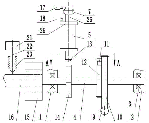
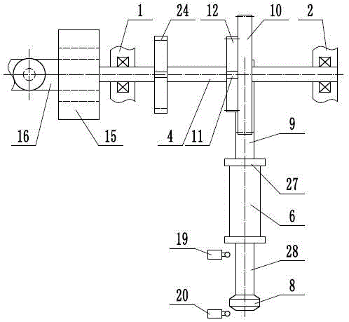
[0014] Such as figure 1 and figure 2 Shown, a kind of index positioning device, it comprises the first support support 1, the second support support 2, the support bearing 3, the output shaft 4, the first oil cylinder 5, the second oil cylinder 6, the first trigger block 7, Second trigger block 8, rack 9, gear 10, pawl 11, ratchet 12, positioning block 13, positioning plate 14, disc clamp 15, shaft workpiece 16, first travel switch 17, second travel switch 18, The third travel switch 19, the fourth travel switch 20, the drill floor 21, the drill bit 22, the guide sleeve 23, the output shaft 4 is rotatably arranged on the first support support 1 and the second support support 2, the output Support bearings 3 are arra


PUM


Abstract

The invention provides an indexing and positioning device, and belongs to the technical field of machining. The indexing and positioning device comprises an output shaft, a rack, a gear, a pawl, a ratchet, positioning blocks and a positioning disc; the ratchet is coaxially fixed on the output shaft; the gear is rotationally arranged on the output shaft; the pawl is mounted on the end surface of the gear; the pawl and the ratchet are engaged; the output shaft is coaxially fixed with the positioning disc; positioning grooves are formed in the positioning disc at equal intervals; the positioning blocks matched with the positioning grooves are arranged at the lower end of a first double-end piston rod of a first oil cylinder; a first trigger block is arranged at the upper end of the first double-end piston rod; a disc fixture is coaxially mounted on one side of the output shaft; a rack of a second oil cylinder is mounted on one side of a second double-end piston rod; the gear and the rack are engaged; and a second trigger block is arranged at the other end of the second double-end piston rod. The indexing and positioning device realizes indexing and positioning of shaft workpieces, facilitates radial porous machining of the shaft workpieces, and is reasonable in structure and high in reliability.

Description


Claims


Application Information

Patent Timeline
Owner 东莞市雅群电子有限公司
Why Eureka
Try Eureka