Removable shunting canopy mechanism

A detachable, carport technology, applied in locomotives, motor vehicles, railway car bodies, etc., can solve problems such as unfavorable remote control operation of shunting locomotives, hidden dangers in the safety of shunting personnel, etc., and achieve the effect of convenient installation and simple use.

Inactive Publication Date: 2016-09-07
CRRC DALIAN CO LTD
View PDF5 Cites 0 Cited by
  • Summary
  • Abstract
  • Description
  • Claims
  • Application Information

AI Technical Summary

Problems solved by technology

Because the shunting personnel can only lean sideways, they can only use one hand to hold the handrail to ensure body balance, and at the same time use the other to operate the remote control locomotive. Such actions are not conducive to the remote control operation of the shunting locomotive. There will also be hidden dangers to the safety of shunting personnel

Method used


Image

  • Removable shunting canopy mechanism
  • Removable shunting canopy mechanism
  • Removable shunting canopy mechanism

Examples


Embodiment Construction

[0017] The present invention will be further described below in conjunction with accompanying drawing.

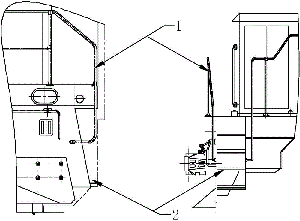
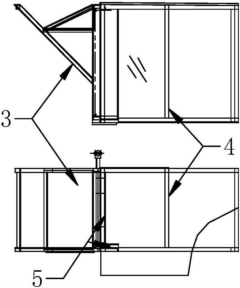
[0018] The present invention is made up of bracket assembly 3 and cover panel assembly 4, and the hinge is connected with bracket assembly 3 and cover panel assembly 4 by riveting, so that these two parts become a whole, such as figure 2 shown.

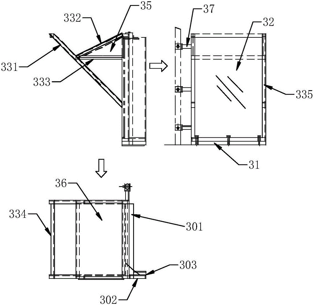
[0019] Bracket assembly 3 consists of square steel one 331, square steel two 332, square steel three 333, square steel four 334, square steel five 335, baffle one 35, baffle two 36, fixed frame 37, tempered glass 32, channel steel one 301, channel steel 2 302, channel steel 3 303, bottom plate 31 and two sets of fasteners, such as image 3 shown. First, square steel one 331, square steel two 3332, square steel three 333, square steel four 334, square steel five 335, baffle one 35, baffle two 36, fixed frame 37, channel one 301, channel two 302, channel steel three 303 are welded together by welding to form an integral frame str...


PUM


Abstract

The invention discloses a removable shunting canopy mechanism. A shunting canopy mechanism is arranged on the left side of the running direction of a locomotive and above the end of the locomotive. The shunting canopy mechanism comprises a holder assembly and a cover plate assembly. The holder assembly and the cover plate assembly are connected through a riveting way. The removable shunting canopy mechanism is convenient and fast to install and convenient to use, the humanization mechanism concept of the modern locomotive is fully embodied, the shunting requirement of shunting work of the locomotive can be met, a good shunting work environment is provided for the shunting operation personnel, and the problem that the shunting operation cannot be conducted safely when a person serves as the shunting person and the driver is avoided.

Description

technical field [0001] The invention relates to the technical field of diesel locomotives. Background technique [0002] Diesel locomotives in outer corridors mostly adopt underframe load-carrying and single-cab body structure. Because the design of the driver's cab must provide a safe, reliable and comfortable working environment for the drivers and passengers, and at the same time, in order to allow a larger operating space inside the driver's cab, the driver's cab is protruded toward the front of the chassis, causing the locomotive to be in adjustment. During the operation of the vehicle, the shunting personnel cannot be in a more suitable position for the shunting operation. [0003] In the shunting of existing diesel locomotives, some diesel locomotives with outer corridors do not have special shunting pedals for shunting. When the shunting personnel and the driver are the same person, in the process of shunting operations, the The personnel leans sideways, puts their...

Claims


Application Information

Patent Timeline
IPC IPC(8): B61D17/00B61C5/00
CPCB61D17/00B61C5/00
Inventor 李冬园郭守相王淑荣王铁峰郭充赵瑞山
Owner CRRC DALIAN CO LTD
Why Eureka
Try Eureka