Interlayer displacement angle measurement apparatus

A measuring device and interlayer displacement technology, which is applied in the direction of angle/taper measurement, etc., can solve the problems that the interlayer displacement angle cannot be directly measured, and it is difficult to ensure the accuracy of small angle measurement, and achieve the effect of improving the measurement accuracy.

Pending Publication Date: 2016-09-28
CENT RES INST OF BUILDING & CONSTR CO LTD MCC GRP
View PDF0 Cites 3 Cited by
  • Summary
  • Abstract
  • Description
  • Claims
  • Application Information

AI Technical Summary

Problems solved by technology

[0004] It can be seen that in the prior art, it is difficult to guarantee the accuracy of small angle measurement by the angle sensor usua

Method used


Image

  • Interlayer displacement angle measurement apparatus
  • Interlayer displacement angle measurement apparatus
  • Interlayer displacement angle measurement apparatus

Examples


Embodiment Construction

[0028] In order to make the technical solutions and advantages of the present invention clearer, the present invention will be further described in detail below in conjunction with the accompanying drawings and specific embodiments.

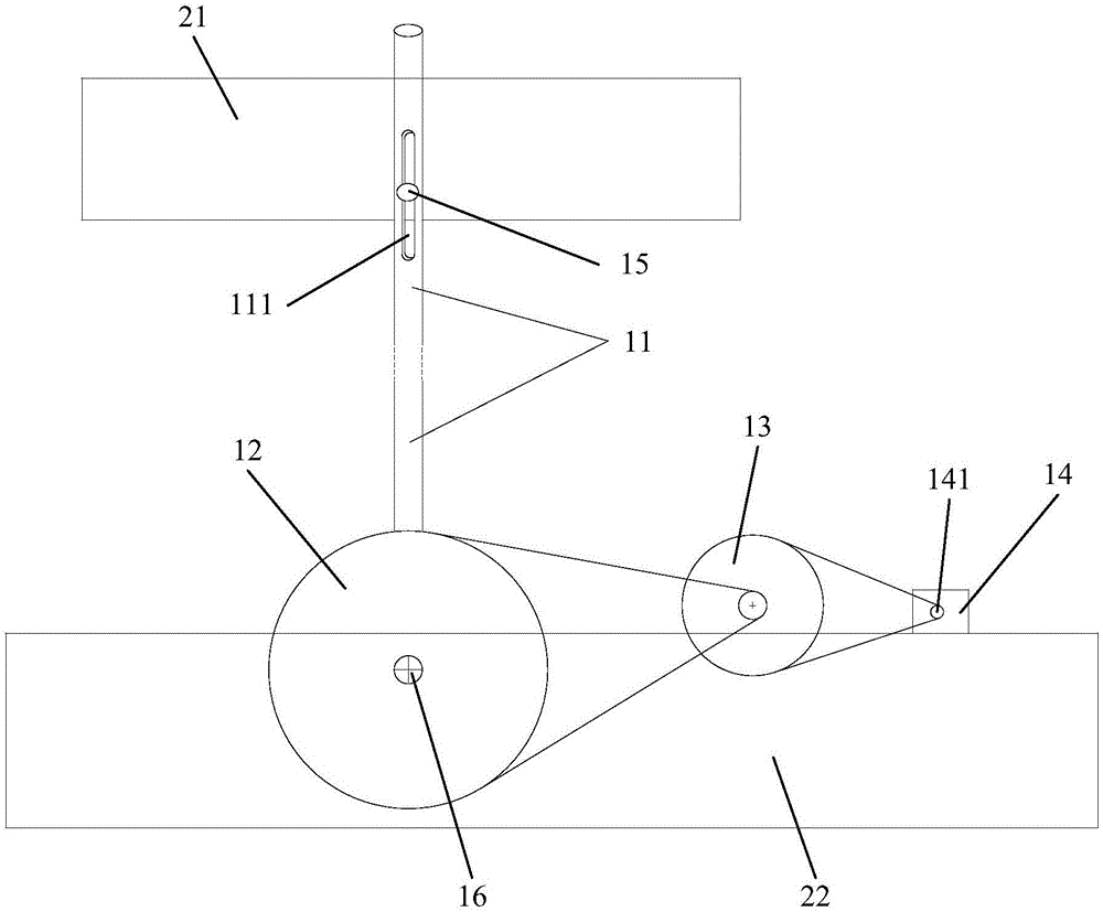
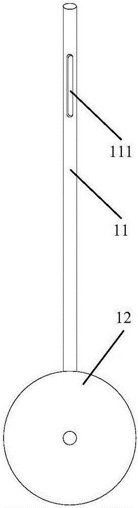
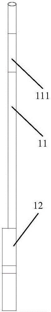
[0029] figure 1 It is a schematic structural diagram of the interlayer displacement angle measuring device in the embodiment of the present invention, figure 2 It is a schematic diagram of the connection between the transmission rod and the first-stage coaxial disk in the embodiment of the present invention, image 3 It is a side view of the connection between the transmission rod and the first-stage coaxial disc in the embodiment of the present invention, Figure 4 It is a structural schematic diagram of the first fixing part and the second fixing part in the embodiment of the present invention, Figure 5 It is a schematic diagram of the connection between the second fixing member and the first-stage coaxial disk in the embodiment of the present


PUM


Abstract

The invention provides a device for measuring interlayer displacement angle, which includes: a transmission rod, a first-stage coaxial disc, a second-stage coaxial turntable and a rotating shaft angle sensor; the upper end of the transmission rod passes through the first fixing part and the upper beam connected, and can slide up and down relative to the first fixing piece; the lower end of the transmission rod is fixedly connected with the first-level coaxial disc; The second fixed part rotates; the second-level coaxial turntable and the rotating shaft type angle sensor are fixed on the beam of this layer; the diameter of the first-level coaxial disc is greater than the diameter of the second-level coaxial turntable; the second-level coaxial turntable The diameter is larger than the diameter of the shaft on the shaft-type angle sensor; the first-stage coaxial disc, the second-stage coaxial turntable and the shaft on the shaft-type angle sensor are all connected by belt transmission or gear transmission. The application of the invention can directly measure the interlayer displacement angle with high precision, and improve the measurement accuracy of the interlayer displacement angle.

Description


Claims


Application Information

Patent Timeline
Owner CENT RES INST OF BUILDING & CONSTR CO LTD MCC GRP
Why Eureka
Try Eureka