Fiber used for laser-mode stripping, and laser-mode stripper applying same

A stripper and mode technology, applied in the direction of lasers, laser components, optical waveguides, etc., can solve the problems of severe heat generation, stripping, aging and deterioration of the stripping effect, etc.

Inactive Publication Date: 2016-09-28
INST OF SEMICONDUCTORS - CHINESE ACAD OF SCI
View PDF4 Cites 13 Cited by
  • Summary
  • Abstract
  • Description
  • Claims
  • Application Information

AI Technical Summary

Benefits of technology

This technology helps prevent damage caused by excessive temperature on an opto-electronic component due to direct absorption or rapid dissipation of energy during use.

Problems solved by technology

Technological Problem addressed during this patented process relates to removing excess or unwanted materials (residuals) that may be left inside an optically active region of a fibre laser's cladding when replacing one type of material used instead of another due to factors like thermal expansion mismatch between different parts within the same system. Existing methods have limitations such as requiring multiple steps and slow cool down times before effective cleanup can occur.

Method used


Image

  • Fiber used for laser-mode stripping, and laser-mode stripper applying same
  • Fiber used for laser-mode stripping, and laser-mode stripper applying same
  • Fiber used for laser-mode stripping, and laser-mode stripper applying same

Examples


Embodiment Construction

[0027] Certain embodiments of the invention will be described more fully hereinafter with reference to the accompanying drawings, in which some, but not all embodiments are shown. Indeed, various embodiments of the invention may be embodied in many different forms and should not be construed as limited to these set forth embodiments; rather, these embodiments are provided so that this invention will satisfy applicable legal requirements.

[0028] In order to make the object, technical solution and advantages of the present invention clearer, the present invention will be described in further detail below in conjunction with specific embodiments and with reference to the accompanying drawings.

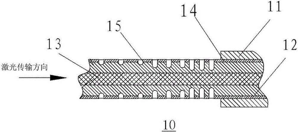
[0029] The present invention provides an optical fiber 10 for laser mode stripping. The optical fiber 10 is made from a finished optical fiber, not an optical fiber in the traditional sense. The above-mentioned finished optical fiber is an optical fiber in the traditional sense.

[0030]


PUM


Abstract

An optical fiber for laser mode stripping and a laser mode stripper using the same, the optical fiber at least includes: a mode stripped section; the mode stripped section includes: a core; and an inner cladding and an inner cladding sequentially coated outside the core The outer cladding, wherein the inner cladding and/or the outer cladding are processed with a plurality of scattering holes for laser mode stripping, and the optical fiber and laser mode stripper have a good laser mode stripping effect.

Description


Claims


Application Information

Patent Timeline
Owner INST OF SEMICONDUCTORS - CHINESE ACAD OF SCI
Why Eureka
Try Eureka