Dual-height RF tuner shield

A technology of radio frequency shielding and shielding covers, which is applied in the field of electronic devices and can solve problems such as rework and/or sample inspection difficulties

Inactive Publication Date: 2016-10-26
THOMSON LICENSING SA
View PDF3 Cites 1 Cited by
  • Summary
  • Abstract
  • Description
  • Claims
  • Application Information

AI Technical Summary

Problems solved by technology

Unfortunately, unibody construction not only requires additional produc

Method used


Image

  • Dual-height RF tuner shield
  • Dual-height RF tuner shield
  • Dual-height RF tuner shield

Examples


Embodiment Construction

[0026] The invention will now be described in more detail with reference to embodiments of the invention shown in the accompanying drawings.

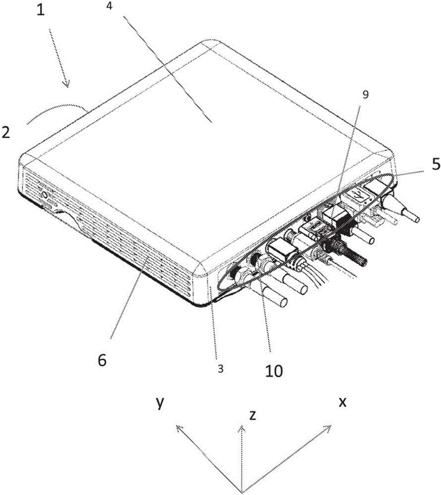
[0027] figure 1 An electronic device 1 of the invention is shown having a front wall 2 , a rear wall 3 , an upper wall 4 and side walls 6 . The electronic device 1 can be a device such as a set-top box (such as a computer, a game console, a DVD player, a CD player, etc.), and can also include a panel socket 5 for connecting a cable 9, wherein one of the electrical connectors can be an F connection Connector 10 or similar connector. This figure shows a plurality of cables 9 connected to electrical connectors on the panel jack 5 , reflecting how crowded the components inside the electronic device 1 are. Therefore, such an electronic device 1, which may have components such as a tuner, requires a tuner shield. In this figure, one of the electrical connectors on the panel jack 5 may be an F-connector 10, or other connector that may be conn


PUM


Abstract

An electronic device is provided that has a vertical chassis wall with an aperture, a horizontal circuit board that extends toward the vertical chassis wall, F-connector connected to the horizontal circuit board and extending out of the a vertical chassis wall through the aperture and dual height inner RF shield that covers part of the F-connector and other electronic components. The height of the RF is greater over the F-connector than over some of the other electronic components.

Description


Claims


Application Information

Patent Timeline
Owner THOMSON LICENSING SA
Why Eureka
Try Eureka