Conveying pipe cleaning device

A technology for cleaning devices and conveying pipes, applied in the direction of cleaning hollow objects, cleaning methods and appliances, chemical instruments and methods, etc., can solve problems such as low cleaning efficiency, damage to conveying pipe sections, and high manual labor intensity, so as to achieve efficient cleaning and avoid damage effect

Active Publication Date: 2016-11-09
河北雷萨重型工程机械有限责任公司
View PDF6 Cites 4 Cited by
  • Summary
  • Abstract
  • Description
  • Claims
  • Application Information

AI Technical Summary

Benefits of technology

This technology allows for efficient removal or maintenance (cleaning) of blockage pipes used during construction projects by fixing them on two components - one drives it towards another while allowing rotation around its axis – which helps remove any stuck material from inside the pipe without damaging itself.

Problems solved by technology

This patented technical problem addressed in this patents relates to managing pipes that become clogged during use for deliverring materials like concrete (pumps). Manual cleanings can be time-consuming and may result in damaged tubular sections while manually removing blocks from inside them requires significant effort. Additionally, reversed pump systems have been developed but they require frequent maintenance because there has always existed some issues where these solutions were effective overtime.

Method used


Image

  • Conveying pipe cleaning device
  • Conveying pipe cleaning device
  • Conveying pipe cleaning device

Examples


Embodiment Construction

[0034] Specific embodiments of the present invention will be described in detail below in conjunction with the accompanying drawings. It should be understood that the specific embodiments described here are only used to illustrate and explain the present invention, and are not intended to limit the present invention.

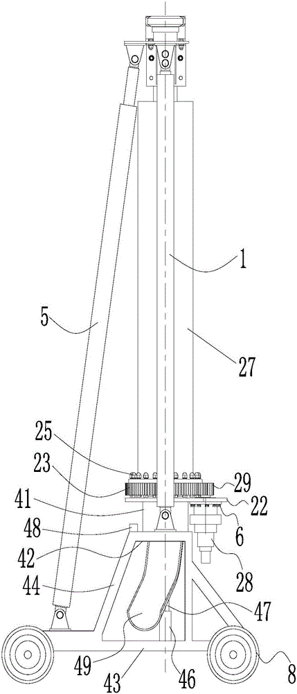
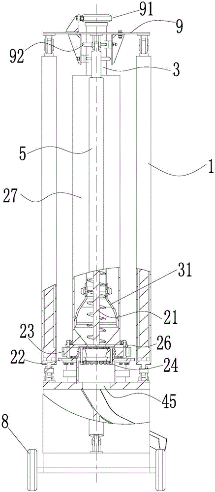
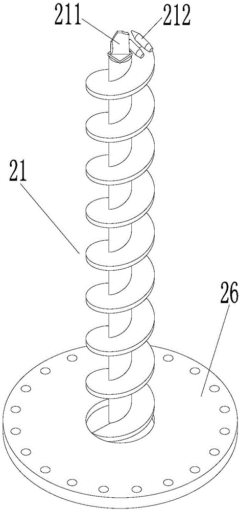
[0035] Such as Figure 1 to Figure 2 As shown, a conveying pipe cleaning device provided by the present invention includes a support base, a rotary mechanism and a first driving part 1. The rotary mechanism is fixed on the support base and includes a rotary assembly and a drill pipe driven to rotate by the rotary assembly. 21. One end of the first driving part 1 is connected to the support base, and the other end is used to fix the delivery pipe 3 and drive the delivery pipe 3 to move axially, so that the drill pipe 21 is screwed into the delivery pipe 3 .

[0036] In the cleaning device provided by the present invention, the blocked conveying pipe 3 is fixed to t


PUM


Abstract

The invention discloses a conveying pipe cleaning device. The device comprises a supporting base, a rotation mechanism and a first drive component (1); the rotation mechanism is fixed to the supporting base and comprises a rotation assembly and a drill rod (21) driven by the rotation assembly to rotate; one end of the first drive component (1) is connected with the supporting base, the other end of the first drive component (1) is used for fixing a conveying pipe (3) and driving the conveying pipe (3) to move in the axial direction, and therefore the drill rod (21) is screwed into the conveying pipe (3); and the cleaning device can efficiently remove concrete in the conveying pipe (3), and operation is easy and convenient.

Description


Claims


Application Information

Patent Timeline
Owner 河北雷萨重型工程机械有限责任公司
Why Eureka
Try Eureka