Roller support of steel truss

A rolling bearing and steel truss technology, which is applied in the field of steel truss trestle, can solve the problems of steel truss being greatly affected by temperature, prone to potential safety hazards, and large elliptical hole of steel truss. Effect

Inactive Publication Date: 2016-11-23
SHANDONG HUANNENG DESIGN INST
View PDF7 Cites 0 Cited by
  • Summary
  • Abstract
  • Description
  • Claims
  • Application Information

AI Technical Summary

Benefits of technology

This patented technical solution described in this patents allows for securely holding up an existing steel truck's frame during use without causing damage from external factors like weather conditions or extreme temperatures. It achieves these benefits through division-upward movements of supports called rollers and rods within the framework itself. These movement helps absorb any thermal variations over time while still providing stable anchoring points for the frames themselves. Additionally, there is no longer one thing needed to fix all bolts individually instead of collectively moving them together. Overall, this design simplifies the process of constructing new buildings quickly and efficiently.

Problems solved by technology

This technical problem addressed in this patented text relates to how to prevent damage from excessive pressure on steels during shipping or handling processes that may cause them to warp up overtime when exposed to different temperatures.

Method used


Image

  • Roller support of steel truss
  • Roller support of steel truss
  • Roller support of steel truss

Examples


Embodiment Construction

[0025] In order to make the purpose, technical solutions and advantages of the embodiments of the present invention clearer, the technical solutions in the embodiments of the present invention will be clearly and completely described below in conjunction with the drawings in the embodiments of the present invention. Obviously, the described embodiments It is a part of embodiments of the present invention, but not all embodiments. Based on the embodiments of the present invention, all other embodiments obtained by persons of ordinary skill in the art without creative efforts fall within the protection scope of the present invention.

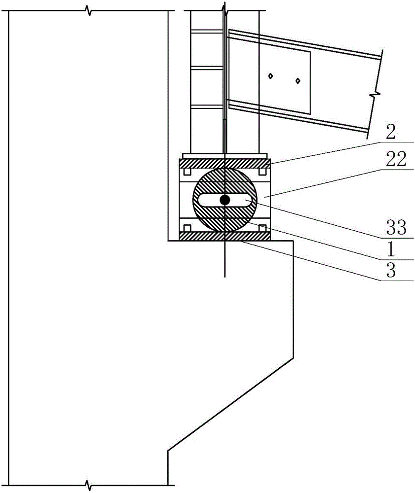
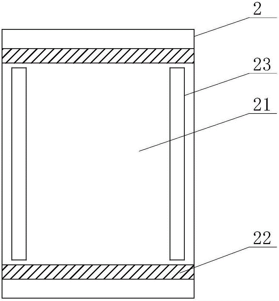
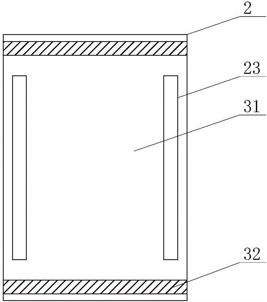
[0026] Such as Figure 1-Figure 7 As shown, a steel truss rolling bearing in this embodiment includes a roller 1, the roller 1 is installed between the upper bearing 2 and the lower bearing 3, and the lower bearing 3 and the upper bearing 2 are interlocked. The upper support 2 includes a top plate 21, the first baffle plate 22 is respectively instal


PUM


Abstract

The invention provides a roller support of a steel truss. The roller support of the steel truss comprises a roller. The roller is installed between an upper support and a lower support and the upper support and the lower support are buckled mutually; the upper support comprises a top plate, first baffles are arranged below the front side and the rear side of the top plate, the lower support comprises a bottom plate, second baffles are arranged above the front side and the rear side of the bottom plate, movable grooves located on the same horizontal level are formed in the lower parts of the first baffles and the upper parts of the second baffles, and the two ends of the roller are arranged in the movable grooves of the two sets of the first baffles and the second baffles. According to the roller support of the steel truss, the support is divided into the upper and lower parts between which the roller is installed, and the upper support and the lower support move relative to each other by taking the roller as the basis, to eliminate the deflection, generated by telescopic deformation under the effect of temperature changes or earthquakes, of a steel truss bridge and generated when the steel truss bridge is loaded, the longitudinal displacement change is released, and the structural safety of the steel truss bridge is improved. The roller support of the steel truss can also resist the effect of crosswise horizontal internal force, such as wind load, equipment load and the like.

Description


Claims


Application Information

Patent Timeline
Owner SHANDONG HUANNENG DESIGN INST
Why Eureka
Try Eureka