Reinforced culvert

A reinforced, culvert technology, applied in the field of culverts, can solve the problems of inconvenient construction, affecting the construction period, and long construction period, and achieve the effect of reducing steel consumption, saving costs and shortening construction period

Active Publication Date: 2013-08-07
NANJING LIANZHONG CONSTR ENG TECH
View PDF5 Cites 18 Cited by
  • Summary
  • Abstract
  • Description
  • Claims
  • Application Information

AI Technical Summary

Benefits of technology

This patented technology relieves pressure from outside during designing buildings' basement structures through various techniques such as filling them with cured concrete (CR), applying high strutting forces between two layers of corrugate steel sheet(C) under heavy loads, creating asymmetrical strong bending stiffening members called stabilizers, increasing their stability, preventing crackings caused by external factors like water waves, and saving money compared to traditional methods. Additionally, these technical features improve efficiency when constructing culverns because they allow more flexibility than previous designs. Overall, this innovative process simplifies building processes, allows for greater utilization of existing infrastructure components, extends lifespan beyond current levels, and lowers overall economic expenses associated therewith.

Problems solved by technology

This patented describes traditional ways that can improve highway constructions by adding cables called boxes into existing structures instead of replacing damaged parts after they've passed over certain sections due to heavy loading. These techniques involve embedding steel bars within the main body of the structure but this may also lead to crackings if there were any issues like insufficient supporting power at critical points where stress concentration occurs. Additionally, current solutions require expensive equipment and lengthy periods of time before being effective.

Method used


Image

  • Reinforced culvert
  • Reinforced culvert
  • Reinforced culvert

Examples


Embodiment Construction

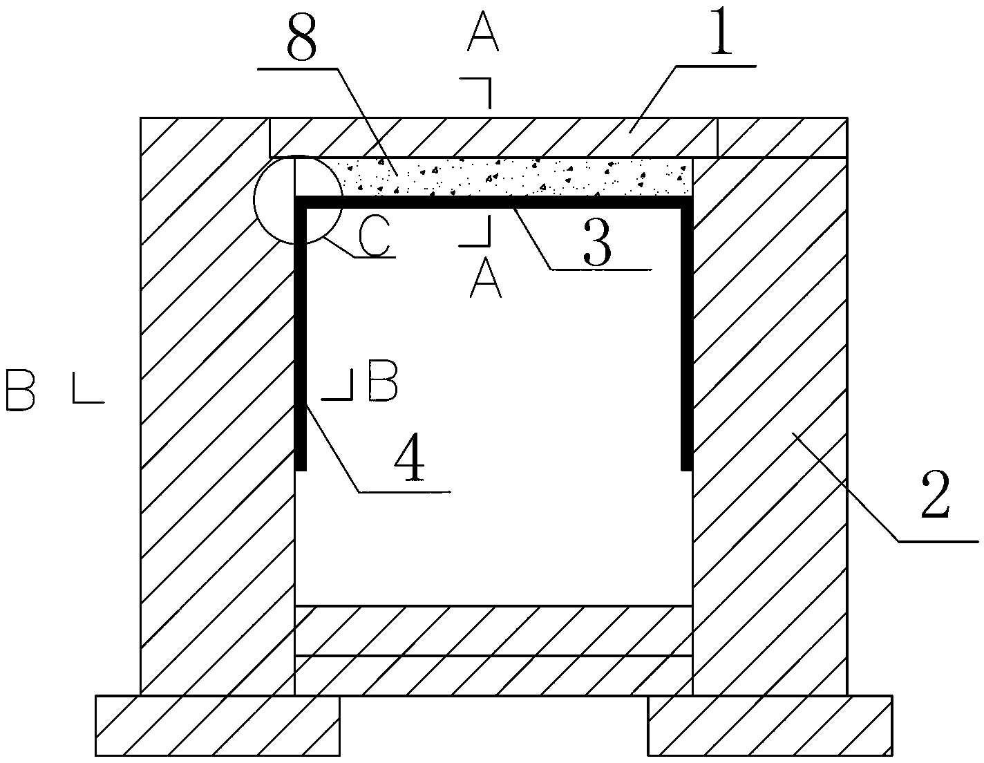
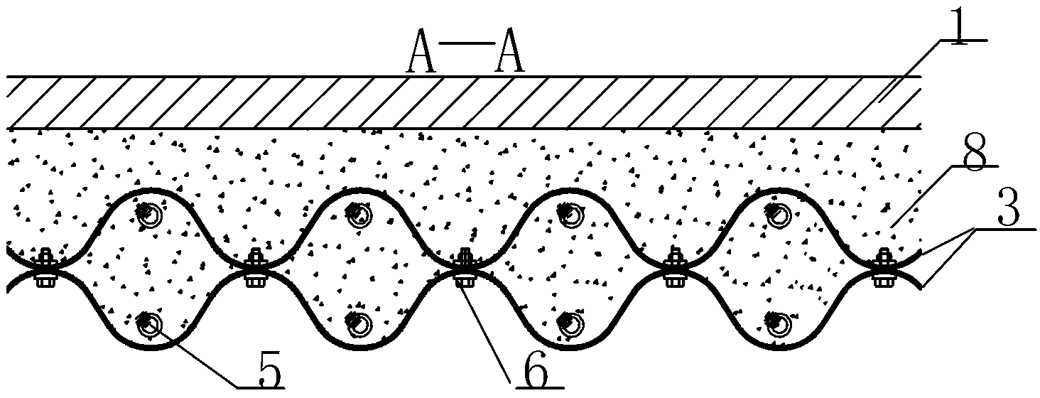
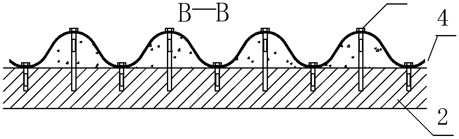
[0012] like Figure 1~4 As shown, the hot-rolled steel plate of Q345 or higher grade is selected in the factory in advance and processed into a standard corrugated steel plate according to the drawing, and the finished rolled threaded steel bar 5 with a sheath is placed on the lower corrugated steel plate, and its tensile strength should be greater than 830Mpa, the yield strength should be greater than 730Mpa, after checking that the position of each component is correct, buckle the upper corrugated steel plate on the lower corrugated steel plate and tighten the corrosion-resistant hot-dip galvanized bolt 6, so that several cavity columns are formed between the two corrugated steel plates body, the thickness of the column is generally more than 220mm, that is, the distance from the wave top to the wave top of the two-layer corrugated steel plate, which is twice the wave height of the corrugated steel plate, and the wave distance of the corrugation is generally greater than 600mm,


PUM


Abstract

The invention discloses a reinforced culvert. The reinforced culvert comprises a culvert top and side walls. A prestress top plate which is composed of a symmetrically fastened double-layer corrugated steel is arranged at the bottom of the culvert top, single-layer corrugated steels are arranged on the inner sides of left and right side walls, the top plate is installed on the single-layer corrugated steels of the side walls, reinforcing steel bars are arranged in a cavity cylinder formed by the double-layer corrugated steel, the cavity cylinder is filled with concrete, and simultaneously, concrete is filled between the culvert top and the prestress top plate as well as between left and right side walls and the single-layer corrugated steels. The reinforced culvert has the advantages that a corrugated steel rigid support is added on the basis of the original culvert structure, and further expansion of cracks is prevented, so that the internal force and deformation of the original culvert structure are reduced greatly, simultaneously, the original structure is fully utilized, and shared force bearing of new and old structures is guaranteed with the using function of the original culvert unchanged.

Description


Claims


Application Information

Patent Timeline
Owner NANJING LIANZHONG CONSTR ENG TECH
Why Eureka
Try Eureka