Hairbrush base plate with dust collection function

A substrate and brush technology, applied in the field of brushes, can solve problems such as poor dust removal function, achieve the effect of improving dust removal effect and realizing dust suction effect

Inactive Publication Date: 2016-12-14
桐乡市永鑫制刷机械厂
View PDF9 Cites 4 Cited by
  • Summary
  • Abstract
  • Description
  • Claims
  • Application Information

AI Technical Summary

Benefits of technology

This patented technology makes it possible for an improved cleaning tool called this brushing material that has its own special feature - there're tiny holes on top where dirt can get stuck during use instead of being removed by other methods like sweeping or vacuuming them away from their surface.

Problems solved by technology

The technical problem addressed by this patented technology relates how current existing hairbrushes remove small particles like dirt but leave them behind when they are being used for cleaning or polishing things that require fine-grained cleansings such as carpets or furniture surfaces.

Method used


Image

  • Hairbrush base plate with dust collection function

Examples


Embodiment 1

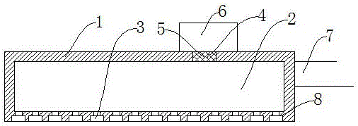
[0012] Such as figure 1 As shown, the substrate of a brush with dust suction function described in this embodiment includes a substrate body 1, the substrate body 1 is a hollow structure, and the interior of the substrate body 1 is a closed cavity 2. The spaced array on one side of the main body 1 has several through holes 3 for installing hair bundles, and the other side of the substrate body 1 is provided with a ventilation hole 4, and a suction fan 6 is provided on the side where the ventilation hole 4 is provided, so that The suction fan 6 mentioned above communicates with the ventilation hole 4; a handle 7 is provided on one side of the substrate body 1 that is not provided with the through hole 3.

[0013] A filter screen 5 is arranged in the ventilation hole 4 .

[0014] The diameter of the end of the through hole 3 outside the substrate body 1 is larger than the diameter of the end inside the substrate body 1 .

[0015] An annular step 8 is arranged in the through hole


PUM


Abstract

The invention relates to the technical field of hairbrushes, in particular to a hairbrush base plate with a dust collection function. The hairbrush base plate comprises a base plate body, the base plate body is of a hollow structure, a closed cavity is formed in the base body, through holes for installing bristle bundles are arrayed in one side face of the base plate body at intervals, a vent hole is formed in the other side face of the base plate body, and a suction fan is arranged on the side face of the vent hole and communicated with the vent hole; a handle is arranged on one side face, without a through hole, of the base plate body. The hairbrush base plate with the dust collection function can achieve the dust collection function by arranging the hollow cavity and the suction fan, and therefore the dust collection effect of the hairbrush is improved.

Description


Claims


Application Information

Patent Timeline
Owner 桐乡市永鑫制刷机械厂
Why Eureka
Try Eureka