Positioning system and method

A positioning system and positioning method technology, applied in the field of positioning systems, can solve the problems of inability to display the specific position of the probe, slow response speed, poor positioning accuracy, etc., and achieve the effects of high reliability, sensitive response, and high positioning accuracy

Inactive Publication Date: 2016-12-14
LANZHOU JIAOTONG UNIV
View PDF8 Cites 0 Cited by
  • Summary
  • Abstract
  • Description
  • Claims
  • Application Information

AI Technical Summary

Problems solved by technology

During the movement of the probe along with the bracket and the connecting rod 5 in the closed cavity, the steel needle will first touch the inner wall of the closed cavity, and a closed DC circuit will be formed at this time, so the bulb will light up, and the experimenter knows that The position of the steel needle ensures the safety of the probe, and plays a rol

Method used


Image

  • Positioning system and method
  • Positioning system and method
  • Positioning system and method

Examples


Example Embodiment

[0028] Embodiments of the present invention will be described in detail below. The examples described below are illustrative and are intended to explain the present invention, but should not be construed as limiting the present invention.

[0029] The technical solution of the present invention will be described in detail below in conjunction with the accompanying drawings and specific embodiments, so as to make the characteristics and advantages of the present invention more obvious.

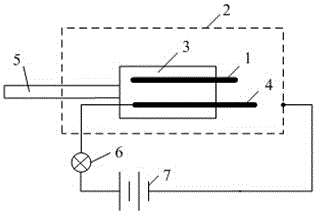
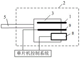
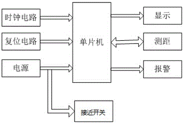
[0030] A positioning system, the positioning system includes a closed cavity 2 and a probe bracket 3 arranged in the closed cavity 2, the probe bracket 3 is fixed with a probe 1, a connecting rod 5, a proximity switch 9 and an ultrasonic wave The distance measuring probe 8, the connecting rod 5 is fixed on the three-dimensional coordinate frame on the periphery of the probe holder 3, and the proximity switch 9 and the ultrasonic distance measuring probe 8 are connected to a single-chip microcomput


PUM


Abstract

The invention discloses a positioning system and method. The positioning system comprises a hardware system and a software system, wherein the hardware system comprises a singlechip, as well as a clock circuit, a reset circuit, a power supply, a display, a distance meter and a sound-light alarm which are respectively connected with the singlechip; the power supply and the singlechip are directly provided with proximity switches; the control system of the singlechip is connected to a drive circuit and a probe bracket; and the software system comprises a control module, as well as a transmission module and a receiving module which are respectively connected with the control module, and the control module is used for controlling startup of the transmission module and the receiving module. The positioning system has the advantages of high positioning accuracy, exact distance measurement, high reliability, small error and sensitive reaction, and can be used for accurately displaying the probe distance and automatically alarming.

Description


Claims


Application Information

Patent Timeline
Owner LANZHOU JIAOTONG UNIV
Why Eureka
Try Eureka