Turbulent burner

A swirl burner and swirler technology, applied in the direction of burner, combustion method, combustion type, etc., can solve the problems of slagging and excessive NOx, achieve the effect of reducing NOx emissions and increasing the concentration of pulverized coal

Active Publication Date: 2017-01-04
SOUTHEAST UNIV
View PDF7 Cites 2 Cited by
  • Summary
  • Abstract
  • Description
  • Claims
  • Application Information

AI Technical Summary

Problems solved by technology

But at the same time, there are some problems with the swirl burner. Because the combustion of the swirl burner is mainly determined by the structure and parameters of the burner itself, unlike the layout of th

Method used


Image

  • Turbulent burner
  • Turbulent burner
  • Turbulent burner

Examples


Embodiment Construction

[0023] The present invention will be further described below in conjunction with the accompanying drawings.

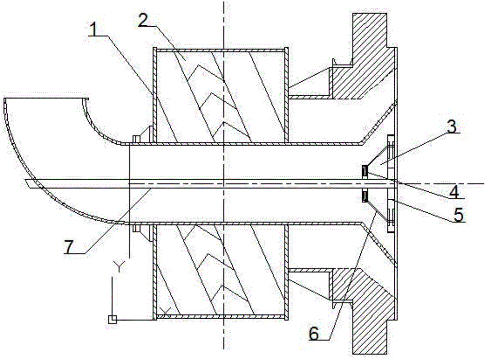
[0024] According to attached figure 1 , a swirl burner, including a primary air channel with a flame stabilizer 3 and a spiral secondary air channel located on the periphery of the primary air channel. The flame stabilizer 3 is arranged at the outlet of the primary air passage, installed on the periphery of the fuel injector 7, and occupies half of the outlet of the primary air passage. The primary air that passes through the flame stabilizer 3 and the primary air that does not pass through the flame stabilizer 3 are respectively referred to as the inner primary air and the outer primary air. The flame stabilizer 3 of the present invention has two functions: first, it can generate internal primary air with adjustable swirl intensity to control the size of the recirculation zone, increase disturbance, and stabilize combustion; Concentrate to form a local high concentrati


PUM


Abstract

The invention discloses a turbulent burner. The turbulent burner comprises a primary air channel and a secondary air channel located on the periphery of the primary air channel. The turbulent burner is characterized in that a flame holder is arranged on an air outlet of the primary air channel, the flame holder comprises a hydrocyclone, a flow expansion channel and a powder coal concentration ring for adjusting swirling intensity, the flow expansion channel is of an external expansion type, the large-section end of the flow expansion channel is connected with the powder coal concentration ring, and the small-section end of the flow expansion channel is connected with the hydrocyclone. The turbulent burner has higher secondary air swirling intensity, higher rigidity and greater smoke suction capacity; the size of a return flow zone can be controlled by adjusting the length of blades on the powder coal concentration ring; secondary air and primary air are mixed later, and emission of NOx can be reduced by locally increasing powder coal concentration.

Description


Claims


Application Information

Patent Timeline
Owner SOUTHEAST UNIV
Why Eureka
Try Eureka