Heat pump system

A heat pump system and heat exchanger technology, applied in lighting and heating equipment, compressors with reversible cycles, refrigerators, etc., can solve the problems of increasing the workload of staff, too many pipelines, etc., and achieve good heating effect, Reduced workload and simple installation structure

Inactive Publication Date: 2017-01-04
SHENZHEN LIBING ENERGY SAVING TECH CO LTD
View PDF6 Cites 1 Cited by
  • Summary
  • Abstract
  • Description
  • Claims
  • Application Information

AI Technical Summary

Benefits of technology

This technology improving its effectiveness by providing better coolings or warming capabilities compared with existing systems that use multiple valves for control purposes. It also simplifies the construction process because it only requires two ways - once they're installed – instead of three times more than usual.

Problems solved by technology

This patented technical problem addressed by this patents relating to current heat pumps that use separate components like an air conditioner condenser (AC) pipe and a throttle valve for both the compression part and the expansion part of the circuit. These systems require more than twice as much space due to their own pipings connecting them together.

Method used


Image

  • Heat pump system
  • Heat pump system
  • Heat pump system

Examples


Embodiment Construction

[0025] In order to make the object, technical solution and advantages of the present invention clearer, the present invention will be further described in detail below in conjunction with the accompanying drawings and embodiments. It should be understood that the specific embodiments described here are only used to explain the present invention, not to limit the present invention.

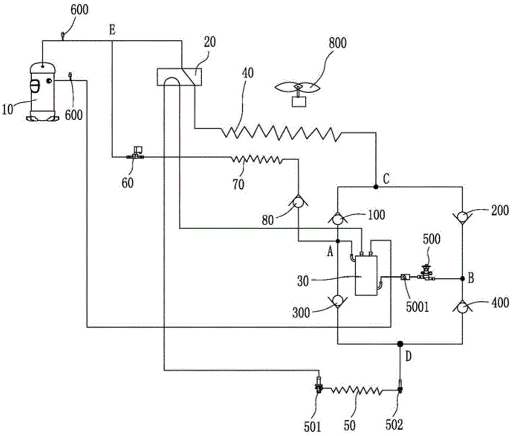
[0026] refer to Figure 1 to Figure 4 As shown, the present invention discloses a heat pump system. Specifically, we describe the structure of a heat pump system in detail. The heat pump system includes:

[0027] A compressor 10, the compressor 10 has a suction port and a discharge port;

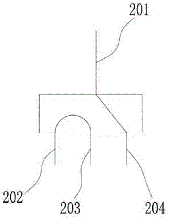
[0028] Four-way reversing valve 20, combined with figure 2 , the four-way reversing valve 20 has an exhaust port 201, a third heat exchanger port 202, an economizer port 203, and a first heat exchanger port 204;

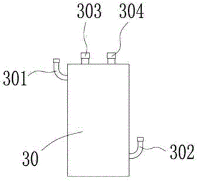
[0029] Economizer 30, combined with image 3 , the economizer has a check valve interface 301, a t


PUM


Abstract

The invention discloses a heat pump system and relates to the technical field of air conditioning equipment. The heat pump system comprises a compressor, a four-way reversing valve, an economizer, a first heat exchanger, a third heat exchanger, a first one-way valve, a third one-way valve, a second one-way valve and a fourth one-way valve, wherein the first one-way valve and the third one-way valve are connected in series and conducting directions of the first one-way valve and the third one-way valve are set in a back-to-back manner; and the second one-way valve and the fourth one-way valve are connected in series and conducting directions of the second one-way valve and the fourth one-way valve are set in a face-to-face manner; a public communication point A is arranged on a pipeline between the first one-way valve and the third one-way valve, and a public communication point B is arranged on a pipeline between the second one-way valve and the fourth one-way valve; the other end of the first one-way valve is conned with the second one-way valve, and a public communication point C is arranged on a pipeline between the first one-way valve and the second one-way valve; and the other end of the third one-way valve is connected with the fourth one-way valve, and a public communication point D is arranged on a pipeline between the third one-way valve and the fourth one-way valve. The heat-pump system has the beneficial effects that a plurality of one-way valves are adopted to form a valve group, so that installing structure is simple, and the workload of workers in the installing process is reduced.

Description


Claims


Application Information

Patent Timeline
Owner SHENZHEN LIBING ENERGY SAVING TECH CO LTD
Why Eureka
Try Eureka