Electric generator wireless monitoring device

A wireless monitoring and generator technology, applied in the direction of computer control, program control, general control system, etc., can solve the problems of inconvenient use, unsatisfactory, large size, etc., and achieve the effect of easy modification, simple modification, and simple device structure.

Inactive Publication Date: 2017-01-04
马忠东
View PDF5 Cites 2 Cited by
  • Summary
  • Abstract
  • Description
  • Claims
  • Application Information

AI Technical Summary

Benefits of technology

This patented technology allows for easy modifications or changes made to an old type machine's electronic components that are used with generators (generating energy). By placing these devices inside their own battery pack instead of connecting them externally through wires, they become more reliable and less expensive than traditional methods like replacing older machines altogether. Additionally, it simplifies construction processes compared to previous designs because there was only one way to connect each component separately from other parts within the unit. Overall, this new design improves efficiency and reduces costs while maintaining its benefits over time.

Problems solved by technology

This patented technology describes two technical problem addressed during the development phase of generators that require periodic testing with various types of instruments like voltmeters and ammetering units (AMUs). These tools have their own limitations due to weight, size, complexity, and lack of portability at remote locations where they may be needed frequently. Additionally, when installing new sensors requires connecting them wirelessly, making it difficult if done outside laborator facilities. Therefore, there was developed a solution called a wireless sensor network (WSN) that allows the generation unit to receive its operating condition from the main machine while being able to transmit detected signals back over radio waves.

Method used


Image

  • Electric generator wireless monitoring device
  • Electric generator wireless monitoring device
  • Electric generator wireless monitoring device

Examples


Embodiment 1

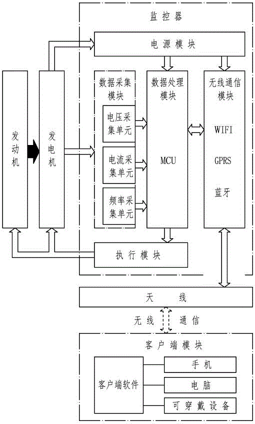
[0048] The generator described in this embodiment is an electric excitation synchronous generator or a multi-pole permanent magnet generator. The former is a traditional small generating set, and the latter is an inverter generating set or a DC charging generating set representing the development direction of a small generating set. The engine is connected with the output end of the crankshaft of the engine, and the electric energy is output under the driving of the engine, and the engine is a gasoline, diesel or gas engine. But obviously the generator wireless monitoring device described in this patent is not limited by the type of generator set, and can also be applied in the fields of solar power generation, wind power generation and human power generation.

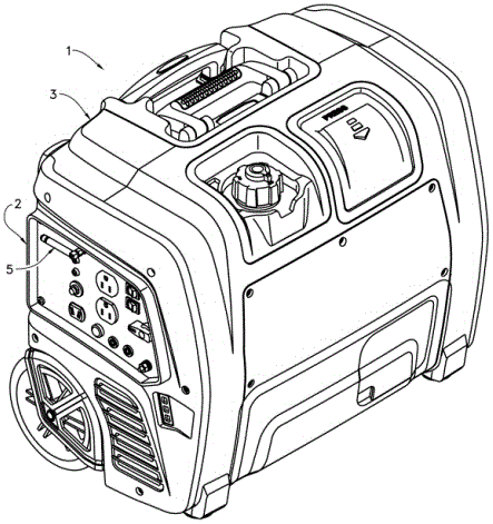
[0049] Such as Figure 1 to Figure 12 As shown, the generator set 1 described in this embodiment is mainly composed of an engine, a generator, a casing 3, an electrical box 2 and an electric control system, the engine is co

Embodiment 2

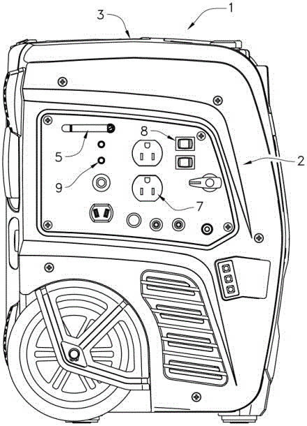
[0071] Such as Figure 13 to Figure 15 As shown, compared with Embodiment 1, the main difference of this embodiment is that the generator described in this embodiment is an open structure without a casing 3, the generator and the engine are installed on the frame 4, and the electrical box 2 is composed of a box The box body 201 is composed of a box cover 202, and the box body 201 is generally a plastic part, which is directly connected with the frame 4. The box cover 202 is generally made of sheet metal and has a plurality of installation holes above it for installing components such as the output socket 7 , the indicator light 9 or the electrical switch 8 .

[0072] Such as Figure 13 to Figure 15 As shown, the antenna 5 of this embodiment is installed on the box cover 202 of the electrical box 2, and the antenna base 503 of the antenna 5 passes through the mounting hole on the box cover 202, and is connected to the box cover 202 through the nut 505 on the antenna connector 504


PUM


Abstract

The invention relates to an electric generator wireless monitoring device. The electric generator wireless monitoring device comprises an electric generator, a monitor and a client side, wherein the monitor acquires state parameters of the electric generator; and the client side is connected with the monitor in a wireless communication mode. The electric generator wireless monitoring device is characterized by further comprising an electrical box and an antenna; the electrical box is arranged on the electric generator; the antenna is used for wireless communication, is arranged on the electrical box, and is connected with the monitor through a conveying wire; the antenna is wirelessly connected with the client side by transmitting and receiving wireless signals; and one of an output socket of the electric generator, an electric switch and an indicator lamp is further arranged on the electrical box at least. The antenna of the electric generator wireless monitoring device is mounted on the electrical box of the electric generator, has the obvious advantages of good wireless communication effect and simple mounting structure, and is good in modification adaptability.

Description


Claims


Application Information

Patent Timeline
Owner 马忠东
Why Eureka
Try Eureka