Novel heat energy recovery device

A new type of heat energy recovery technology, applied in indirect heat exchangers, transportation and packaging, fluid heaters, etc., can solve problems such as blockage of ventilation pipes, limited recovery effect, and limit the performance and scope of application of recovery devices, to ensure normal The effect of operation and full recycling

Inactive Publication Date: 2017-01-25
CHENGDU XUNDE SCI & TECH
View PDF4 Cites 5 Cited by
  • Summary
  • Abstract
  • Description
  • Claims
  • Application Information

AI Technical Summary

Problems solved by technology

However, due to structural and design constraints, the recovery effect of existing recovery devices is often limited, and the full utilization of heat energy has not been realized.
At the same time, although the high-temperature waste gas in the production process has been purified before being discharged, it is inevitable that there will still

Method used


Image

  • Novel heat energy recovery device

Examples


Embodiment Construction

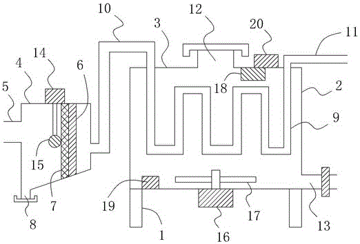
[0013] Such as figure 1 As shown, a new type of heat energy recovery device includes a bracket 1 and a water tank 2 located on the bracket 1. A tank cover 3 is also provided on the top of the water tank 2, and a filter cavity 4 is provided on the left side of the water tank 2. After filtering The left side wall of the cavity 4 is connected with an air intake pipe 5, and the right side wall of the filter cavity 4 is provided with a cavity air outlet, and a vertically arranged dividing plate 6 is also provided inside the filter cavity 4. The plate 6 is evenly provided with a plurality of partition through holes, and a filter screen 7 close to the partition 6 is also provided on the left side of the partition 6, and a cleaning port 8 is also provided at the bottom left end of the filter cavity 4, A cover is also provided at the cleaning port; at least one S-shaped heat dissipation pipe 9 is also provided inside the water tank 2, and the air inlet of the S-shaped heat dissipation pip


PUM


Abstract

The invention relates to a novel heat energy recovery device. The novel heat energy recovery device comprises a support, a water tank and a tank cover, wherein a filtration cavity is formed in the left side of the water tank, a gas inlet pipe is connected to the left side wall of the filtration cavity, a cavity gas outlet is formed in the right side wall, a partition board is arranged in the filtration cavity, partition board through holes are formed in the partition board, a filter net is arranged on the left side of the partition board, a clearing port and a lid body are arranged at the left end of the bottom of the filtration cavity, an S-shaped heat dissipation pipe is arranged in the water tank, a gas inlet of the S-shaped heat dissipation pipe communicates with the cavity gas outlet in the filtration cavity through a gas guide pipe, the gas outlet is connected with an exhaust pipe, a water inlet is formed in the tank cover, a water outlet is formed in the bottom of the right side of the water tank, a push rod motor is arranged at the top end outside the filtration cavity, the bottom end of a push rod of the push rod motor is connected with a brush rod, a rotation motor is arranged at the bottom end of the outside of the water tank, and a stirring rod is arranged at the top end of an output shaft of the rotation motor. By the aid of the structure, heat energy can be more sufficiently recovered and utilized, and normal operation of the heat energy recovery device is effectively guaranteed.

Description


Claims


Application Information

Patent Timeline
Owner CHENGDU XUNDE SCI & TECH
Why Eureka
Try Eureka