Cave depot air conditioner unit

A technology of air-conditioning units and caverns, applied in air-conditioning systems, space heating and ventilation, household heating, etc., can solve problems such as engineering concealment, and achieve the effect of solving concealment

Active Publication Date: 2017-02-01
浙江盾安机电科技有限公司
View PDF3 Cites 6 Cited by
  • Summary
  • Abstract
  • Description
  • Claims
  • Application Information

AI Technical Summary

Problems solved by technology

[0003] The technical problem to be solved by the present invention is to provide a cavern air-con

Method used


Image

  • Cave depot air conditioner unit
  • Cave depot air conditioner unit
  • Cave depot air conditioner unit

Examples


Embodiment Construction

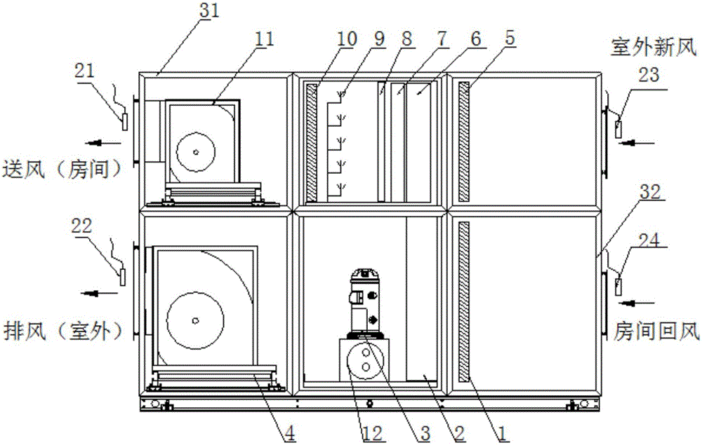
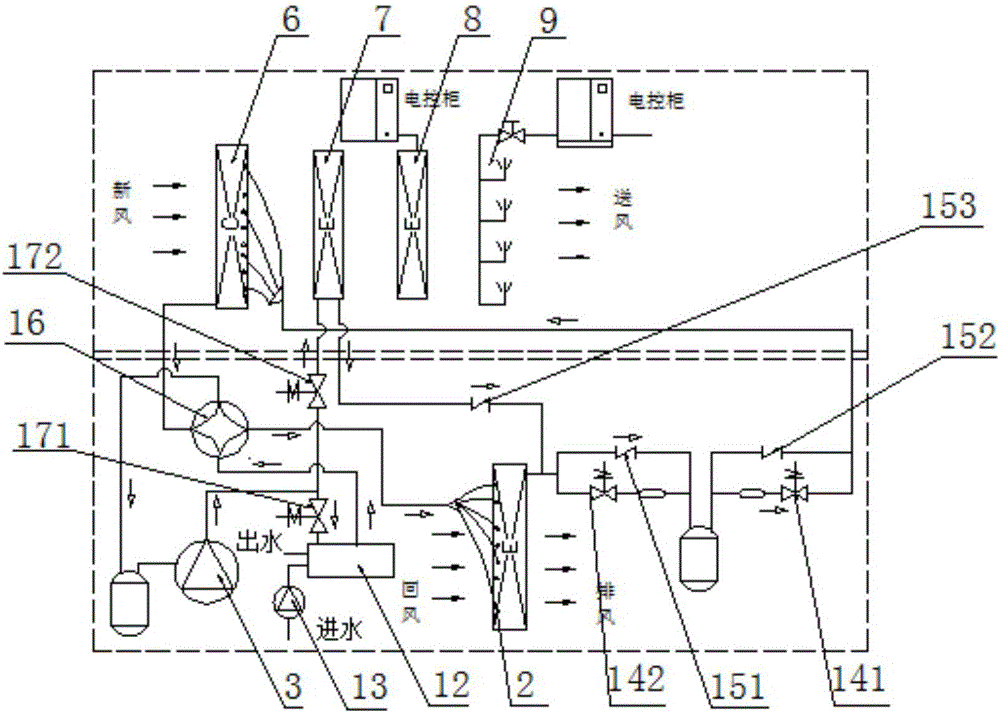
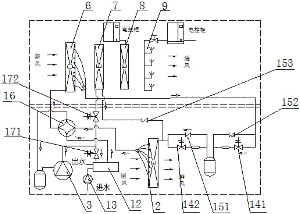
[0024] Such as Figure 1 to Figure 3 As shown, a cavern air conditioning unit includes a compressor 3, a first proportional regulating valve 171, a water side heat exchanger 12, a four-way valve 16, a first heat exchanger 2, a second heat exchanger 6, a first One-way valve 151, second one-way valve 152, third one-way valve 153, first throttle valve 141, second throttle valve 142, reheater 7, electric heater 8, high-pressure micro-mist humidifier 9, Blower 11, exhaust fan 4. Wherein, the water-side heat exchanger 12 is supplied with water by a water pump 13, and an exhaust air temperature and humidity sensor 22 is arranged at the exhaust air outlet of the air conditioning unit, and a fresh air temperature and humidity sensor 23 and a fresh air filter 5 are arranged at the fresh air inlet of the air conditioning unit. Air supply temperature and humidity sensor 21 is provided at the air supply port of the unit, and return air temperature and humidity sensor 24 and return air filter


PUM


Abstract

The invention discloses a cave depot air conditioner unit which comprises a compressor, a first proportional regulating valve, a water side heat exchanger, a four-way valve, a first heat exchanger, a second heat exchanger, a first one-way valve, a second one-way valve, a first throttling valve and a second throttling valve. The water side heat exchanger provides return water through a water pump. An exhaust temperature and humidity sensor is arranged at the position of an exhaust outlet of the air conditioner unit. A fresh air temperature and humidity sensor is arranged at the position of a fresh air inlet of the air conditioner unit. A control system can compare the temperature of the exhaust temperature and humidity sensor with the temperature of the fresh air temperature and humidity sensor while the air supply temperature meets the requirement, the flow of the water pump is automatically adjusted, the temperature difference between the temperature of the exhaust temperature and humidity sensor and the temperature of the fresh air temperature and humidity sensor is controlled within a preset range so that the purpose of disguising can be achieved, and the problem about concealing of the underground project is solved.

Description


Claims


Application Information

Patent Timeline
Owner 浙江盾安机电科技有限公司
Why Eureka
Try Eureka