Hall sensor and assembling method thereof

A Hall sensor and sensor technology, which is applied to the housing of magnetic sensors, the geometric arrangement of magnetic sensing elements, and instruments, etc., can solve the problems of high scrap rate, difficult operation, and large damage to the cable surface, and achieve simple installation process , Improve the effect of product qualification rate

Pending Publication Date: 2017-02-01
BEIJING AISENBOWEI TECH DEV CO LTD
View PDF0 Cites 0 Cited by
  • Summary
  • Abstract
  • Description
  • Claims
  • Application Information

AI Technical Summary

Problems solved by technology

The assembly method of the Hall sensor is as follows: first, put the combination of the 4 sets of sensors and the control board into the flange bottom shell, fit the bottom surface well, and adjust the phase between the 4 sets of sensors and the flange holes, as shown in image 3 As shown, the phases of sensors 1, 2, 3, and 4 in the figure relative to the mounting holes of the flange have a very important impact on the detection accuracy, so after the phase is adjusted, sol curing treatment is required. This sol curing process requires 4-6 hours, the following problems often occur during this process: during the curing process of the 4 sets of sensors that have been adjusted in phase, due to factors such as gravity or movement, the phase changes, resulting in a high scrap rate
After the combination of the 4 groups of sensors and the control board is adjusted in phase and the sol is cured, put the cable compression nut, stud bolt connector, hoop nylon ring and tail pipe on the cable in sequence, and then weld the cable connector to the control board , after the welding is completed, pull down the tail pipe, hoop nylon ring, stud bolt joint and cable compression nut to the installation position in sequence, such as Figure 4 It can be seen that before the cable is welded to the control board, there is a downward distance L between the position of the hoop nylon ring on the cable and the final actual installation of the hoop. After the cable is welded to the control board, the tail pipe needs to be screwed. Insert the flange bottom shell, and then pull down the hoop nylon ring to the actual installation hoop position. This pulling process is difficult to operate, and the damage to the cable surface is relatively large, which is not conducive to mass production.

Method used


Image

  • Hall sensor and assembling method thereof
  • Hall sensor and assembling method thereof
  • Hall sensor and assembling method thereof

Examples


Example Embodiment

[0039] In order to make the technical problems, technical solutions and advantages to be solved by the present invention clearer, the following will describe in detail with reference to the drawings and specific embodiments.

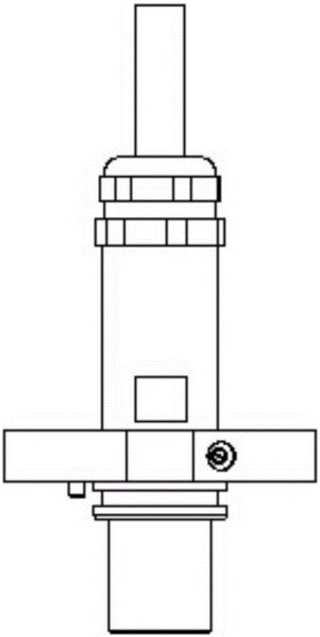
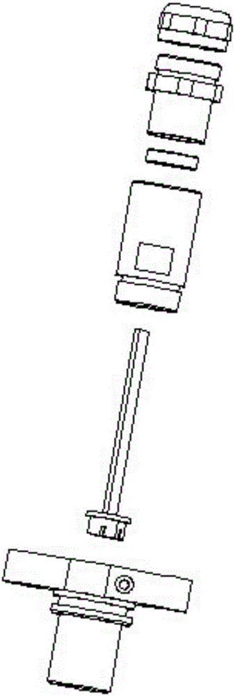
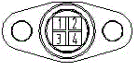
[0040] like Figure 5 , Figure 7 As shown, a Hall sensor, including cable 1, cable compression nut 2, stud bolt joint 3, hoop nylon ring 4, control board 5, 4 sets of sensors 6 and flange bottom shell 7, as described in 4 sets The sensor 6 is located at the lower end of the control board 5, the upper end of the control board 5 is connected to the lower end of the cable 1, and the nylon ring 4, the stud bolt joint 3 and the cable compression nut 2 are sequentially installed on the on the cable 1, and the hoop nylon ring 4 is directly passed through its working position on the cable 1 before the welding of the cable 1 and the control board 5, and the working position is adjacent to the upper part of the connection between the cable 1 and the control board 5


PUM


Abstract

The invention provides a hall sensor and an assembling method thereof. The hall sensor comprises a cable, a cable pressing nut, a double-headed bolt joint, a hoop nylon ring, a control board, four groups of sensors and a flange bottom shell, wherein the flange bottom shell comprises a disc-type flange bottom shell piece and a tube-type flange bottom shell piece; a central hole is arranged in the disc-type flange bottom shell piece; the control board carrying the four groups of sensors is inserted in the tube-type flange bottom shell piece and is cured through a sol, and the tube-type flange bottom shell piece is inserted with the disc-type flange bottom shell piece through the central hole. The phase adjustment process between the four groups of sensors and a flange mounting hole is carried out after sol curing; by using the slewability of a circumference, mounting between the tube-type flange bottom shell piece with the sensors cured and the disc-type flange bottom shell piece is carried out on a test bed, the mounting process is simpler and more convenient than that of the traditional hall sensor, phases of the four groups of sensors do not change, and the product qualification rate is greatly improved.

Description


Claims


Application Information

Patent Timeline
Owner BEIJING AISENBOWEI TECH DEV CO LTD
Why Eureka
Try Eureka