Pyrolysis experiment device monitoring system

A technology of a test device and a monitoring system, which is applied in the field of hardware implementation of the monitoring system, can solve the problems of inconvenient unified operation, single function, and inability to record and save historical data of temperature and humidity, so as to avoid repeated design and facilitate industrial promotion , the effect of simple operation

Inactive Publication Date: 2017-03-15
SHENWU TECH GRP CO LTD
View PDF3 Cites 2 Cited by
  • Summary
  • Abstract
  • Description
  • Claims
  • Application Information

AI Technical Summary

Problems solved by technology

[0005] Its disadvantages are: the function is too single, and the real-time curve display and historical data cannot be recorded and saved for temperature and humidity; for the good effect of controlling the external temperature and humidity regulation mechanism, the single-chip control algorithm is not easy to realize; the hardware and software dev

Method used


Image

  • Pyrolysis experiment device monitoring system

Examples


Example Embodiment

[0037] The specific implementations of the present invention will be described in more detail below with reference to the accompanying drawings and embodiments, so as to better understand the solutions of the present invention and the advantages of various aspects thereof. However, the specific embodiments and examples described below are for illustrative purposes only, and are not intended to limit the present invention.

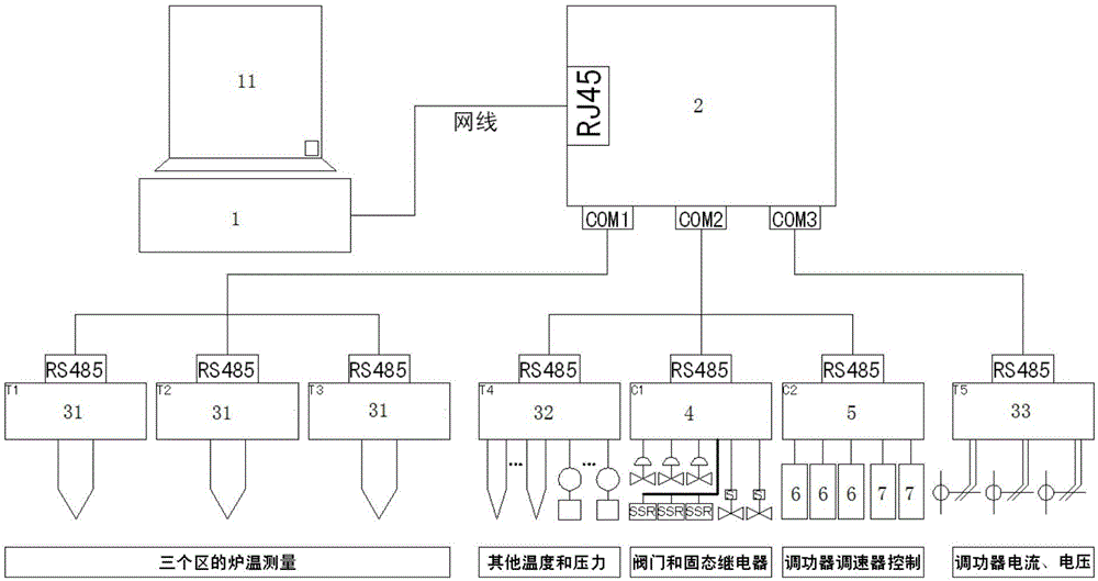
[0038] To better describe the present invention, first introduce the pyrolysis test device. The pyrolysis test device is composed of a pyrolysis furnace, a feeding part, a heating and conveying part, a slag discharge part, an oil gas discharge part, an auxiliary nitrogen gas and a steam part. The main body of the pyrolysis furnace is composed of three heating pipes wound by resistance wires, forming three temperature zones of the furnace body; feeding and heating are mainly composed of two screw conveyors. The temperature in the pyrolysis furnace is provided by


PUM


Abstract

The invention provides a pyrolysis experiment device monitoring system, which is used for monitoring a pyrolysis experiment device. The system comprises an industrial control computer, a serial server, a measurement module, a digital quantity output module and an analog quantity output module. The industrial control computer serves as a host for monitoring the system. The serial server is connected with the industrial control computer through an Ethernet. The measurement module is connected with the serial server through a ModBus RTU protocol. The digital quantity output module is used for outputting a voltage signal, and controlling a pneumatic lock hopper valve, a solenoid valve and a solid-state relay of the pyrolysis experiment device; and the digital quantity output module is connected with the serial server through the ModBus RTU protocol. The analog quantity output module is used for outputting an analog quantity signal and controlling a power regulator and a speed regulator of the pyrolysis experiment device; and the analog quantity output module is connected with the serial server through the ModBus RTU protocol. The monitoring system is simple to operate, and can realize curve display in real time and historical data recording and keeping.

Description


Claims


Application Information

Patent Timeline
Owner SHENWU TECH GRP CO LTD
Why Eureka
Try Eureka