Tube-wound heat exchanger with separated core and shell

A technology of wound-tube heat exchangers and core shells, applied in indirect heat exchangers, heat exchanger types, heat exchanger shells, etc., can solve the problems of traditional structures that are difficult to process and manufacture, so as to prevent pipe rupture and improve design The effect of precision

Active Publication Date: 2018-11-20
SHANGHAI JIAO TONG UNIV +1
View PDF7 Cites 0 Cited by
  • Summary
  • Abstract
  • Description
  • Claims
  • Application Information

AI Technical Summary

Problems solved by technology

[0007] Aiming at the above-mentioned deficiencies in the prior art, the present invention proposes a coil-wound heat exchanger with separated core and shell, which solves the problem that the traditional struct

Method used


Image

  • Tube-wound heat exchanger with separated core and shell
  • Tube-wound heat exchanger with separated core and shell
  • Tube-wound heat exchanger with separated core and shell

Examples


Embodiment 1

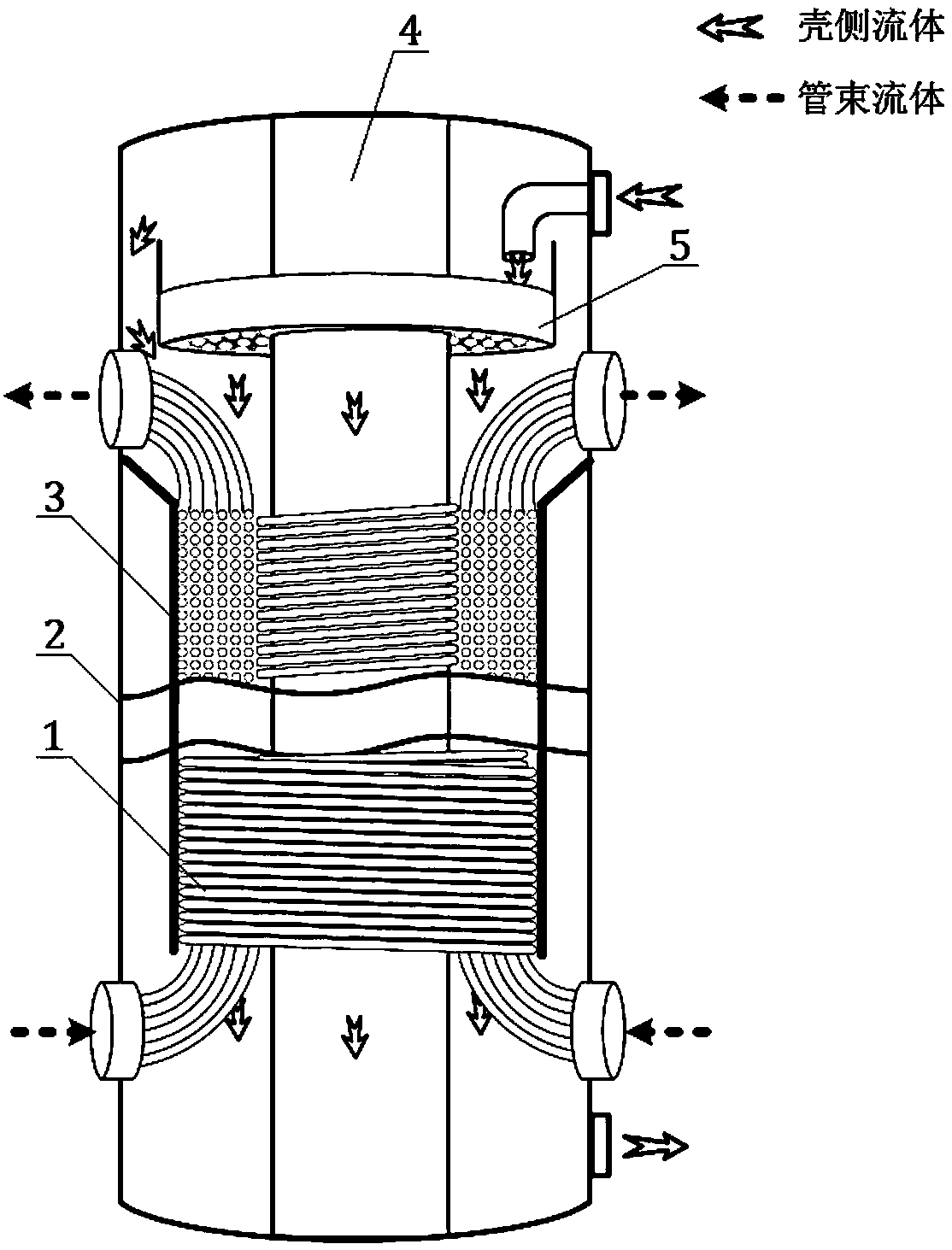
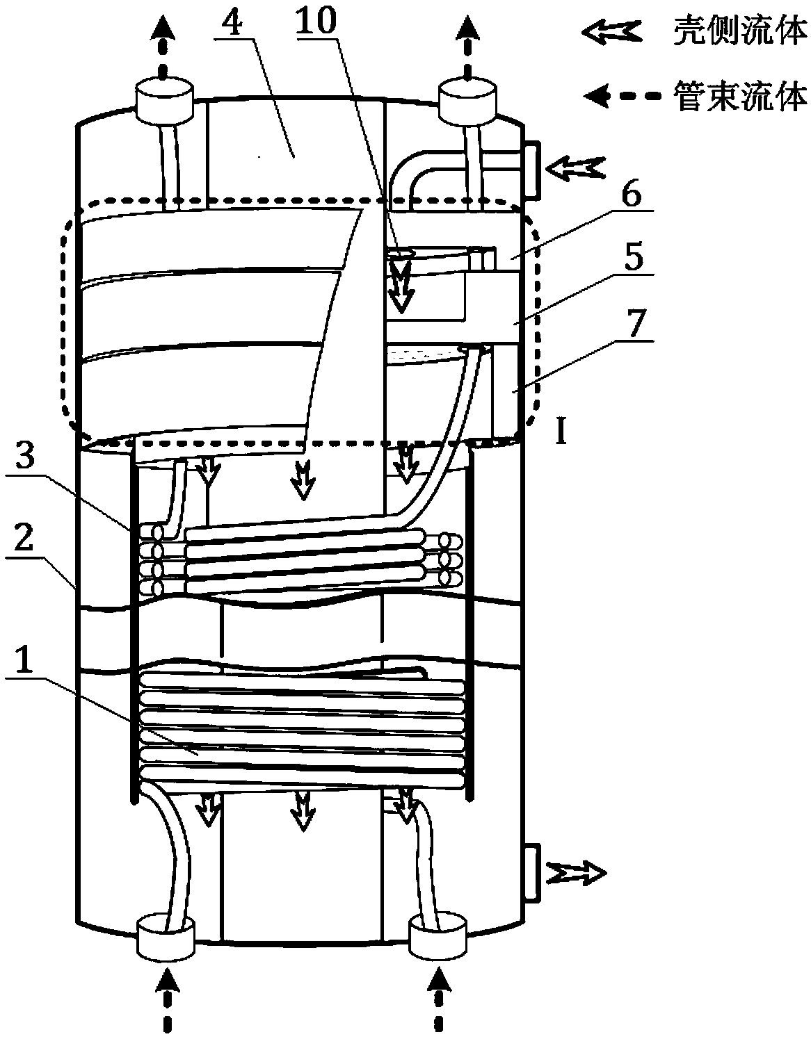
[0024] Such as figure 2 with image 3 As shown, this embodiment includes a central cylinder 4, a groove-type homogenizer 5, and an annular sealing section 7 arranged in the housing. The central cylinder 4 is arranged in the housing 2 to form an annular cavity between the two. The distributor 5 is nested in the housing 2 and sleeved on the central cylinder 4, the annular sealing section 7 is nested in the housing 2 and connected to the bottom of the homogenizer 5, and the sleeve 3 is disposed in the annular cavity and sleeved On the annular sealing section 7;

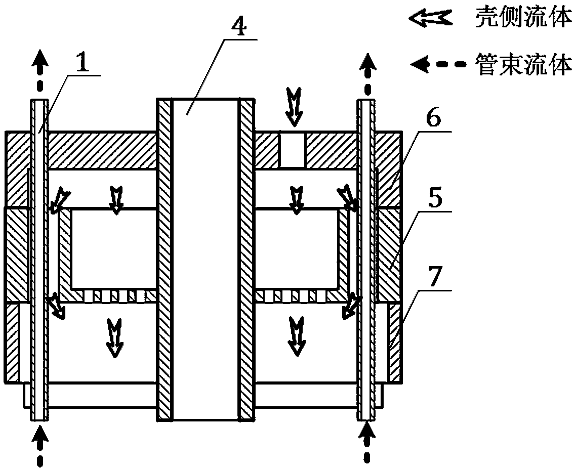
[0025] Such as image 3 with Figure 4 As shown, the bottom plate of the homogenizer 5 is symmetrically provided with two gas phase circulation holes 9 near the edge, and the bottom plate of the homogenizer 5 is uniformly distributed with a plurality of liquid phase circulation holes 8 except for the gas phase circulation holes 9.

[0026] The diameter of the liquid phase circulation hole 8 is 0.2 mm-2 mm; the gas phase circul


PUM


Abstract

The invention discloses a core shell separated wound tube heat exchanger, and belongs to the technical field of low temperature heat exchange. The core shell separated wound tube heat exchanger comprises a shell, a sleeve, a center tube, a uniform distributor and an annular sealing section which are sequentially arranged from outside to inside, wherein an annular cavity is formed between the center tube and the shell; the uniform distributor of a groove-shaped disc structure and the annular sealing section are sequentially embedded at the outer part of the sleeve; the annular sealing section is connected with the bottom of the uniform distributor; a plurality of wound tubes are arranged inside the sleeve; one ends of the wound tubes directly stretch out of the bottom of the uniform distributor; the other ends of the wound tubes stretch out of the top of the uniform distributor through gas phase circulation holes; and a plurality of uniformly distributed liquid phase circulation holes and the plurality of symmetrical gas phase circulation holes are formed in the uniform distributor. According to the core shell separated wound tube heat exchanger, the problem that after the heat exchanger is miniaturized, a traditional structure is difficult to process and manufacture can be solved, and the core shell separated wound tube heat exchanger can be utilized in amplification tests of industrial heat exchange devices in natural gas liquefaction.

Description


Claims


Application Information

Patent Timeline
Owner SHANGHAI JIAO TONG UNIV
Why Eureka
Try Eureka