Tray

A tray and coordination technology, which is applied in the direction of rigid containers, bottle/can parts, containers, etc., can solve the problems that the panel cannot be put into the Tray, the difference in length direction is large, and the glass shakes violently, so as to achieve packaging compatibility , Prevent damage to the panel and save packaging cost

Active Publication Date: 2017-04-26
WUHAN CHINA STAR OPTOELECTRONICS TECH CO LTD
View PDF9 Cites 4 Cited by
  • Summary
  • Abstract
  • Description
  • Claims
  • Application Information

AI Technical Summary

Benefits of technology

This patented technology allows for better flexibility in accommodating various types of display devices such as smart phones due to their sizes. By adjusting certain parameters like thicknesses and materials used during manufacturing processes, these displays may work properly even if they don't fit perfectly within each other. Additionally, by reducing the risk of damage caused on the edges of the screen, the useable space inside the device increases while still maintaining its functionality. Overall, this innovation improves productivity efficiency and cost savings compared to traditional designs.

Problems solved by technology

This patented technical problem addressed by this patents relates to how to protect smaller display devices from being scratched or bent when they come into contact with other objects on their owners’ desks.

Method used


Image

  • Tray
  • Tray
  • Tray

Examples


Embodiment Construction

[0030] The details of the present invention can be understood more clearly with reference to the accompanying drawings and the description of specific embodiments of the present invention. However, the specific embodiments of the present invention described here are only for the purpose of explaining the present invention, and should not be construed as limiting the present invention in any way. Under the teaching of the present invention, the skilled person can conceive any possible deformation based on the present invention, which should be considered as belonging to the scope of the present invention, and the present invention will be further described below in conjunction with the accompanying drawings.

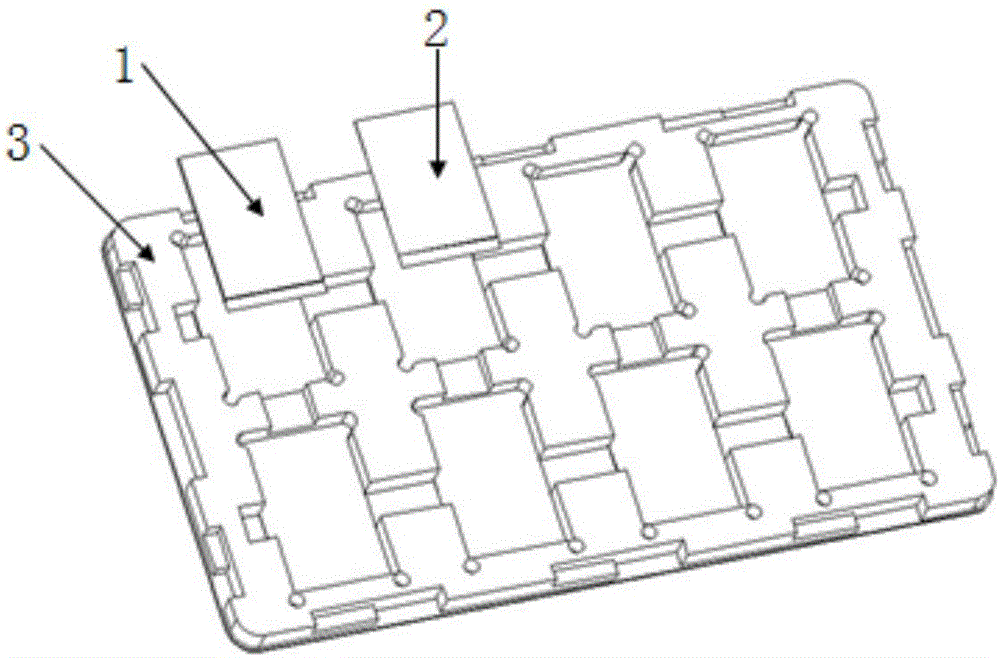
[0031] Figure 5 to Figure 11 Respectively, the structural representation of the tray of the present invention, Figure 5 Partial enlarged schematic diagram of middle part C, structural schematic diagram of inlay, perspective view of inlay, schematic diagram of assembly of


PUM


Abstract

The invention discloses a tray. The tray comprises a tray body and inserts, wherein the tray body is provided with multiple columns of grooves which can stably contain panels, the grooves are arranged at intervals, the two sides of each groove are provided with protrusions, the intermediate region of each protrusion is provided with a coordination groove which communicates with the grooves, the coordination grooves in the two sides of each groove are oppositely arranged, the first end of each insert is arranged in the corresponding coordination groove in a clamped mode, the second end of each insert is arranged outside the corresponding coordination groove in a protruding mode and extends into the corresponding groove, and the width of the second end is smaller than or larger than that of the first end. The tray is simple in structure, packaging compatibility of the tray is achieved by means of different assembling manners of the inserts, complexity for controlling packing materials is effectively reduced, and meanwhile the packaging cost is reduced.

Description


Claims


Application Information

Patent Timeline
Owner WUHAN CHINA STAR OPTOELECTRONICS TECH CO LTD
Why Eureka
Try Eureka