Novel grid turnover plow
A technology for turning plows and fences, which is applied in the direction of plows, agricultural machinery and implements, etc. It can solve the problems of insufficient turning force of the soil layer, increased power consumption of cultivated land, unfavorable land maintenance and crop growth, etc., to reduce resistance and reduce power consumption. Consumption, promotion of recycling and landfill, beneficial effect of straw returning to the field
- Summary
- Abstract
- Description
- Claims
- Application Information
AI Technical Summary
Benefits of technology
Problems solved by technology
Method used
Image

Examples
Embodiment 1
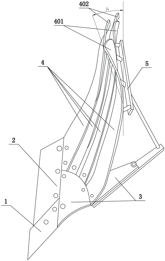
[0027] like figure 1 As shown, a new type of grid bar turning plow comprises a plow shovel tip 1, a plow shovel 2 and a plow wall. They are all installed on the plow holder 3, and the plow holder 3 is installed on the girder through the plow post and the girder holder of the plow body assembly. There is a gap, and the front end of the grid bar 4 is detachably installed on the plow holder 3 through bolts. Among all the grid bars 4 that make up the plow surface, the tail of the upper grid bar 4 is provided with a front bend 401 downward, and the lower grid bar The tail end of 4 is bent 402 to its back, and the backs of all grid bars 4 are connected by connecting frame 5 . Among all the grid bars 4 forming the plow surface, the bending angle A of the front bend 401 of the uppermost grid bar 4 is 40°.
[0028] When in use, the downward front bending 401 of the tail of the upper grid bar 4 will give the turned-up soil a downward pressure, which can promote the soil to turn over, can
Embodiment 2
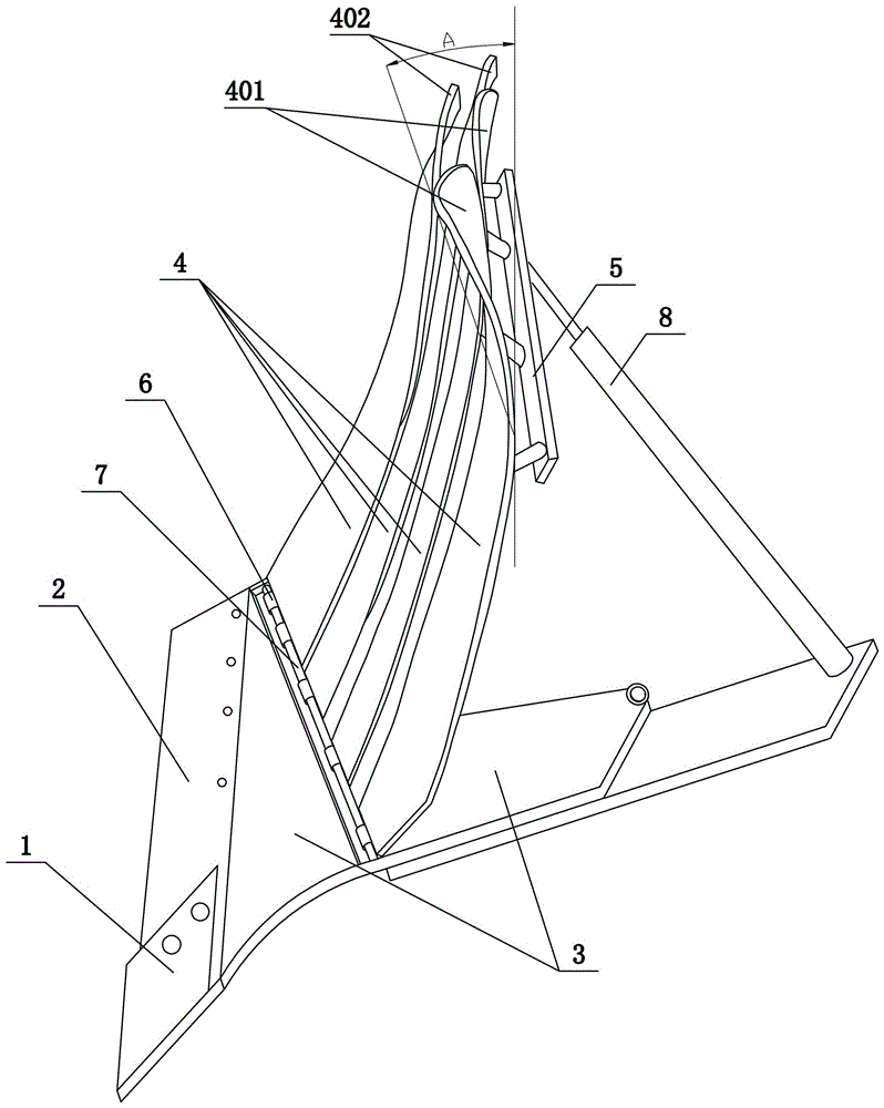
[0030] like figure 2 As shown, repeating Example 1, there are the following differences: the front end of the grid bar 4 is provided with a hook 6, the plow stock 3 is provided with a hook column 7, and the grid bar 4 is hung on the hook column by the hook 6 7, the connecting frame 5 on the back of the grid bar 4 is connected to the plow holder 3 through a connecting piece 8. The connecting piece 8 is an air cylinder or a hydraulic cylinder or a screw thread that cooperates with each other.
[0031] When in use, the grid bar 4 is hooked on the hook column 7, and the grid bar 4 can rotate around the hook column 7. The plow holder 3 is connected to the plow holder 3 through an air cylinder or a hydraulic cylinder or a screw nut that cooperates with each other, and the grid bar can be adjusted according to different plot soils. The overall inclination angle of bar 4 can be adjusted forward to improve the performance of weed coverage; adjusted backward to reduce resistance and redu
Embodiment 3
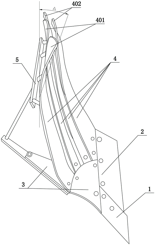
[0033] like image 3 Shown, repeat embodiment one, have the following differences: the bending direction of grid bar 4 in the present embodiment is opposite to the bending direction of grid bar 4 in embodiment one, and both are symmetrical to each other, when the overturning plowing of embodiment one, Soil turns to the right, and when the turning plow of the present embodiment plows the land, the soil turns to the left.
PUM
 Abstract
Description
Claims
Application Information
 - R&D Engineer
- R&D Manager
- IP Professional
- Industry Leading Data Capabilities
- Powerful AI technology
- Patent DNA Extraction
Browse by: Latest US Patents, China's latest patents, Technical Efficacy Thesaurus, Application Domain, Technology Topic.
© 2024 PatSnap. All rights reserved.Legal|Privacy policy|Modern Slavery Act Transparency Statement|Sitemap