Electro-hydraulic speed reducer

A technology of electro-hydraulic reducer and reducer, which is applied in the direction of track brakes, railway car body parts, transportation and packaging, etc., and can solve problems such as unfavorable railway equipment troubleshooting, large sleeper board spacing, and increased single load of public sleeper boards.

Inactive Publication Date: 2017-05-10
TIANJIN RAILWAY SIGNAL
View PDF8 Cites 0 Cited by
  • Summary
  • Abstract
  • Description
  • Claims
  • Application Information

AI Technical Summary

Benefits of technology

The inventor's new type hydraulically powered electric machine reduces its size while maintaining their efficiency compared to older machines that had been designed for them.

Problems solved by technology

This patented problem addressed in this patents relates to improving the performance or durability of elec-Hydrogen Reducers (EHR) due to their high pressure requirements compared to traditional hydrostatic reduction gears such as ball screw mechanisms. Additionally, current methods require frequent replacements of components after installation, leading to increased costs associated with maintaining them.

Method used


Image

  • Electro-hydraulic speed reducer
  • Electro-hydraulic speed reducer

Examples


Embodiment Construction

[0020] It should be noted that, in the case of no conflict, the embodiments of the present invention and the features in the embodiments can be combined with each other.

[0021] In describing the present invention, it should be understood that the terms "center", "longitudinal", "transverse", "upper", "lower", "front", "rear", "left", "right", " The orientations or positional relationships indicated by "vertical", "horizontal", "top", "bottom", "inner" and "outer" are based on the orientations or positional relationships shown in the drawings, and are only for the convenience of describing the present invention and Simplified descriptions, rather than indicating or implying that the device or element referred to must have a particular orientation, be constructed and operate in a particular orientation, and thus should not be construed as limiting the invention. In addition, the terms "first", "second", etc. are used for descriptive purposes only, and should not be interpreted as


PUM


Abstract

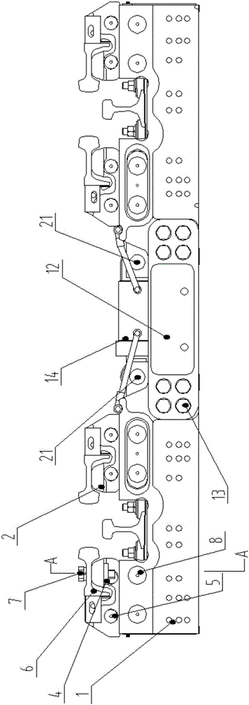
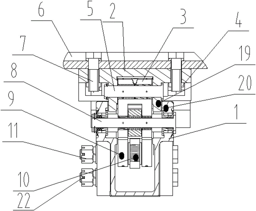
The invention provides an electro-hydraulic speed reducer which comprises bases, a braking rail base, connecting plates, a crank throw, a connecting rod, a braking rail and an oil cylinder. The two bases are fixed together through two connecting plates, the two connecting plates are located on the front side and rear side between the two bases respectively, the oil cylinder is connected above the bases through an oil cylinder shaft, a braking rail is fixed to the braking rail base through fixing bolts, the fixing bolts are located on two sides of the braking rail base, the upper portion of the crank throw is close to the upper end of the braking rail base, and the lower portion of the braking rail base is embedded into the inner side of the base. The electro-hydraulic speed reducer adopts a single-cylinder braking mechanism of a double-clamp and flat-pushing brake mechanism and does not need adjustment of a distance between sleeper plates and installation of ballast beds replacing the sleeper plates, and constriction cost can be reduced. The oil cylinder is located above the sleeper plates, and convenience is brought to repair and maintenance. The connecting rod is close to a rail base to prevent rainwater invasion and soaking, and the service life is prolonged. The maintenance times of the oil cylinder are decreased, and the maintenance cost of the oil cylinder is reduced.

Description


Claims


Application Information

Patent Timeline
Owner TIANJIN RAILWAY SIGNAL
Why Eureka
Try Eureka