Improved manual release device for electro-hydraulic disc brake

A disc brake and manual release technology, applied in the direction of brake actuators, etc., can solve the problems of inconvenient operation of manual pumps, not very smooth, causing accidents, etc.

Active Publication Date: 2016-01-06
JIANGXI HUAWU BRAKE
View PDF5 Cites 0 Cited by
  • Summary
  • Abstract
  • Description
  • Claims
  • Application Information

AI Technical Summary

Problems solved by technology

[0004] 1. The manual pump is sometimes inconvenient to operate. Due to the fixed installation position, it is not very easy to operate in the small space of the machine room in many cases, resulting in inconv

Method used


Image

  • Improved manual release device for electro-hydraulic disc brake
  • Improved manual release device for electro-hydraulic disc brake
  • Improved manual release device for electro-hydraulic disc brake

Examples


Embodiment Construction

[0027] The present invention will be further described below in conjunction with the accompanying drawings and specific embodiments. The following examples are only used to illustrate the present invention, and are not intended to limit the protection scope of the present invention.

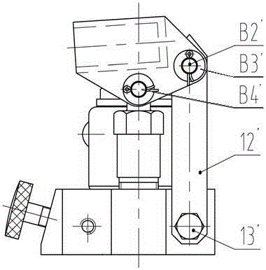
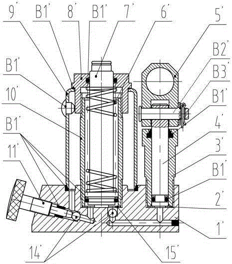
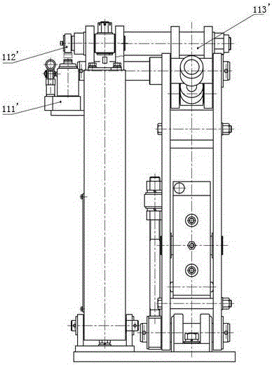
[0028] Such as image 3 , Figure 3a , Figure 3b As shown, an improved manual release device for electrohydraulic disc brakes of the present invention includes a base 1, an operating cylinder 3, a piston rod A7, a booster rod seat 6, a connecting rod 17, a rotating support 4, a working Oil cylinder 10, piston rod B13 and oil tank 11,

[0029] Both the operating cylinder 3 and the working cylinder 10 are fixed on the base 1, the operating cylinder 3 is connected with the base 1 through threads, the piston rod A7 and the operating cylinder 3 are in clearance fit, and are sealed by the sealing ring B4 to prevent the hydraulic oil from leaking out. The afterburner rod seat 6 is connected with the p


PUM


Abstract

The invention discloses an improved manual release device for an electro-hydraulic disc brake. The improved manual release device comprises a base, an operating oil cylinder, a piston rod A, a force application rod seat, a connecting rod, a rotary support, a working oil cylinder, a piston rod B and an oil tank, wherein the operating oil cylinder is communicated with the oil tank through an oil way; a steel ball is arranged in the middle of the oil way for blocking; the working oil cylinder is communicated with the oil tank through two oil ways; a steel ball is arranged in the middle of the first oil way for blocking and is tightly pressed by an unloading screw; the second oil way is blocked by a safety electromagnetic valve; the operating oil cylinder is communicated with the working oil cylinder through an oil way; and a steel ball is arranged in the middle of the oil way for blocking. The function of the improved manual release device is that under the condition of power failure, the brake is opened manually or the brake is manually opened when a pusher of the brake is in failure; and in addition, the device is equipped with the safety electromagnetic valve, the accident potential caused by the fact that braking cannot completed during baking because pressure is forgotten to be relieved when the brake is opened due to maintenance or emergency power off is avoided.

Description


Claims


Application Information

Patent Timeline
Owner JIANGXI HUAWU BRAKE
Why Eureka
Try Eureka