Speed reducer efficiency detection device
A technology of efficiency detection and reducer, which is applied in the direction of measuring devices, testing of mechanical components, testing of machine/structural components, etc., can solve the problems of detecting reducers and achieve high detection efficiency
- Summary
- Abstract
- Description
- Claims
- Application Information
AI Technical Summary
Problems solved by technology
Method used
Image

Examples
Example Embodiment
[0041] Example 1
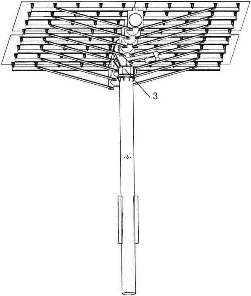
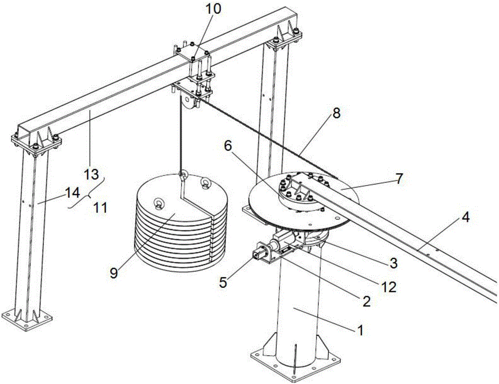
[0042] Reference Figure 2-5 In this embodiment, the fixed platform includes a support column 1 and a support platform 2. The support column 1 is used to support the reducer, and the support platform 2 is used to support the motor 5, torque sensor, etc.; the support column 1 is vertically arranged, and the reducer 3 is installed on the top of the support column 1; the support platform 2 is arranged perpendicular to the height direction of the support column 1, and the support platform 2 is arranged horizontally and fixedly connected to the side of the support column 1. Of course, in other embodiments, the structure of the fixed platform is not limited to the above, and can also be adjusted according to specific conditions, which is not limited here.
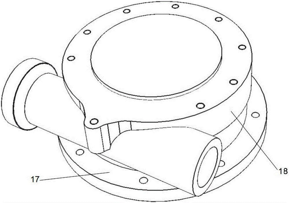
[0043] In this embodiment, the reducer includes a reducer housing 18, a reducer base 17 arranged at the bottom of the housing, and a gear transmission mechanism 18 arranged in the reducer housing. The reducer is mounte
Example Embodiment
[0056] Example 2
[0057] Reference Figure 6-7 This embodiment is a modification made on the basis of embodiment 1. Compared with the embodiment, there are the following differences:
[0058] In this embodiment, the reducer 3 is provided with a planetary reduction mechanism 19 and a gear transmission mechanism, and the motor 5 is connected to the planetary reduction mechanism 19 and the gear transmission mechanism in sequence transmission, and torque sensors are provided between each other; specifically, such as Figure 7 As shown in the figure, the output end of the motor 5 is connected to the input end of the first torque sensor 12 through the first coupling 21, and the output and input end of the first torque sensor 12 is connected to the input end of the planetary reduction mechanism 19 through the second coupling 22 , The output end of the planetary reduction mechanism 19 is connected to the input end of the second torque sensor 20 through the third coupling 23, and the output e
PUM
 Abstract
Description
Claims
Application Information
 - R&D Engineer
- R&D Manager
- IP Professional
- Industry Leading Data Capabilities
- Powerful AI technology
- Patent DNA Extraction
Browse by: Latest US Patents, China's latest patents, Technical Efficacy Thesaurus, Application Domain, Technology Topic.
© 2024 PatSnap. All rights reserved.Legal|Privacy policy|Modern Slavery Act Transparency Statement|Sitemap