Operation monitoring system of hot-line working robot

A technology for live work and work monitoring, applied in the electric power field, can solve the problems of no monitoring scheme, the safety of power grids, robots and operators cannot be guaranteed, and the start of late.

Inactive Publication Date: 2017-05-31
NANJING UNIV OF SCI & TECH
View PDF4 Cites 12 Cited by
  • Summary
  • Abstract
  • Description
  • Claims
  • Application Information

AI Technical Summary

Benefits of technology

This patented technology allows for real-time monitoring during machine stoppage or other situations where there may be problems happening around it. It uses this collected data to identify potential issues before they occur, allowing operators to react accordingly more quickly than traditional methods like manual inspections.

Problems solved by technology

The technical problem addressed in this patented text relates to improving safe operation of electricity grid workers without requiring them physically inspecting each machine manually over long distances due to its height above sea level.

Method used


Image

  • Operation monitoring system of hot-line working robot
  • Operation monitoring system of hot-line working robot
  • Operation monitoring system of hot-line working robot

Examples


Embodiment Construction

[0018] It is easy to understand that, according to the technical solution of the present invention, without changing the spirit of the present invention, those skilled in the art can imagine various implementations of the live working robot operation monitoring system of the present invention. Therefore, the following specific embodiments and drawings are only exemplary descriptions of the technical solution of the present invention, and should not be regarded as the entirety of the present invention or as a limitation or limitation on the technical solution of the present invention.

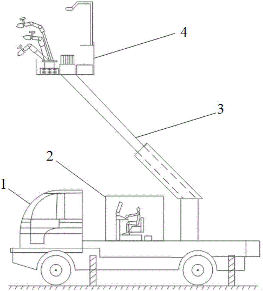
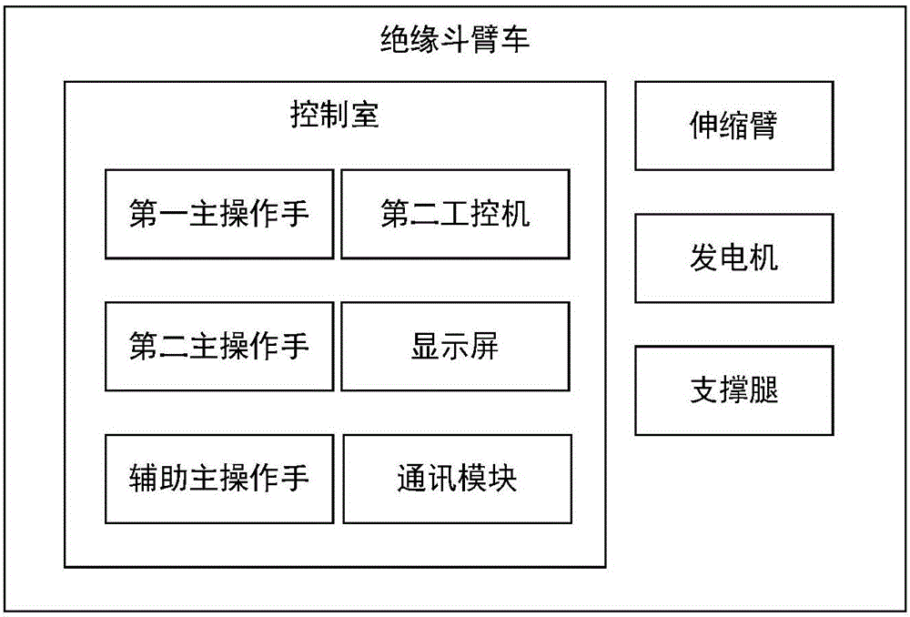
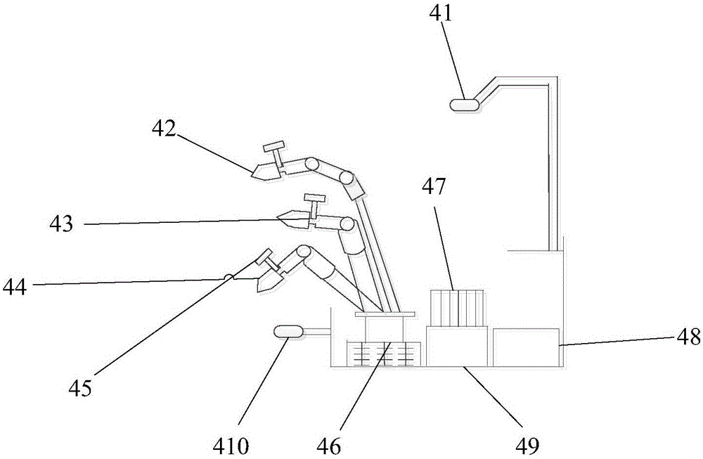
[0019] With reference to the accompanying drawings, the live working robot used in the monitoring system includes an insulated bucket truck 1 , a control room 2 , a telescopic arm 3 , and a robot platform 4 . Among them, the control room 2 and the telescopic arm 3 are erected on the insulated bucket truck 1, and the end of the telescopic arm 3 is connected to the robot platform 4, and the fiber opti


PUM


Abstract

The invention provides an operation monitoring system of a hot-line working robot. Monitoring objects include a first mechanical arm, a second mechanical arm, an auxiliary mechanical arm, a storage battery and an operation scene. Monitoring equipment of the monitoring system includes a temperature and humidity sensor, a pressure sensor, a current collector, a voltage collector, a data collection card, a panoramic camera, a binocular camera and a depth camera, data which are collected by the temperature and humidity sensor, the pressure sensor, the current collector and the voltage collector are compared with corresponding safe range values, if the current collected data are within corresponding safe ranges, the hot-line working robot is normally operated, and if the current collected data are not within the corresponding safe ranges, corresponding warning messages are sent. According to the operation monitoring system, operation personnel can remotely monitor the robot to work on line through the monitoring system, so that the safety of the operation personnel is guaranteed.

Description


Claims


Application Information

Patent Timeline
Owner NANJING UNIV OF SCI & TECH
Why Eureka
Try Eureka