Photoelectrochemical biosensor and preparation method thereof

A biosensor and photoelectrochemical technology, applied in the field of biosensing, can solve the problems of difficult miniaturization of photoelectrochemical biosensors, and achieve the effects of simple structure, small device size and high sensitivity

Active Publication Date: 2017-05-31
SHENZHEN UNIV
View PDF11 Cites 6 Cited by
  • Summary
  • Abstract
  • Description
  • Claims
  • Application Information

AI Technical Summary

Problems solved by technology

[0004] In view of the above-mentioned deficiencies in the prior art, the object of the present invention is to provide a photoelectrochemical biosensor and a preparation method there

Method used


Image

  • Photoelectrochemical biosensor and preparation method thereof
  • Photoelectrochemical biosensor and preparation method thereof
  • Photoelectrochemical biosensor and preparation method thereof

Examples


Embodiment 1

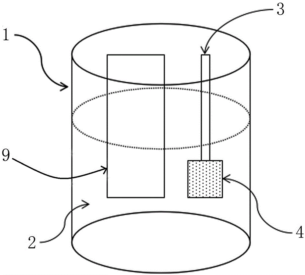
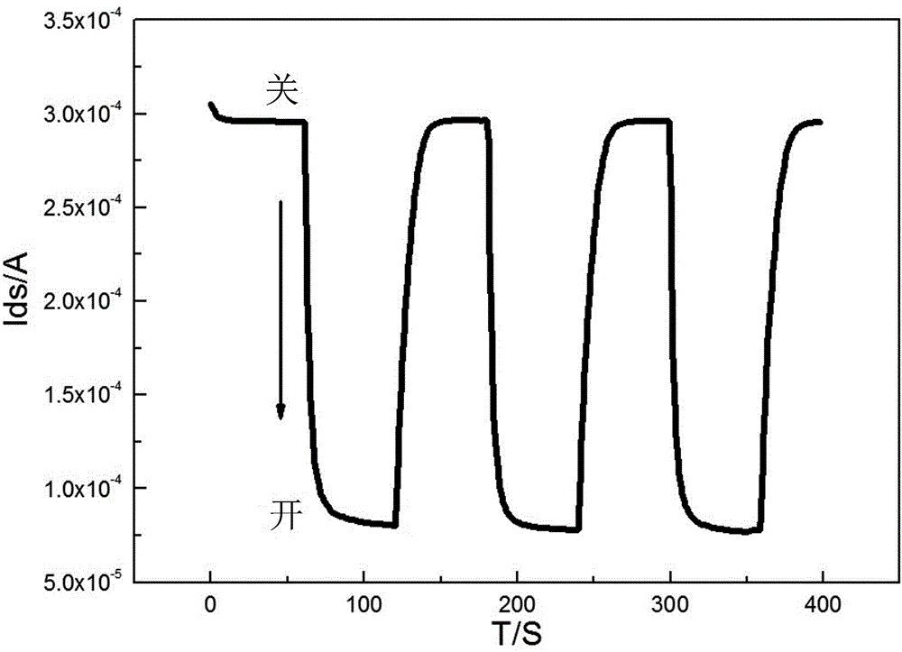
[0047] Example 1 Photoelectrochemical DNA sensor based on organic electrochemical transistor

[0048] Principle: The gate electrode is an ITO electrode assembled with cadmium sulfide quantum dots (CdS QDs). Under light conditions, when the energy of the light is greater than the energy required for the electron transition in CdS, the electrons in the valence band in CdS will transition to the conduction band. , forming electron-hole pairs. When the electrons in the conduction band are injected into the electrode, the electron donor in the solution provides electrons to the holes in the valence band, which will form a photocurrent. The generation of this current will reduce the potential of the electrolyte / gate electrode interface, thereby increasing the applied on the OECT device. effective gate voltage. The channel current of OECT is given by the following equation:

[0049]

[0050] where q stands for electron charge, µ stands for hole mobility, represents the initial

Embodiment 2

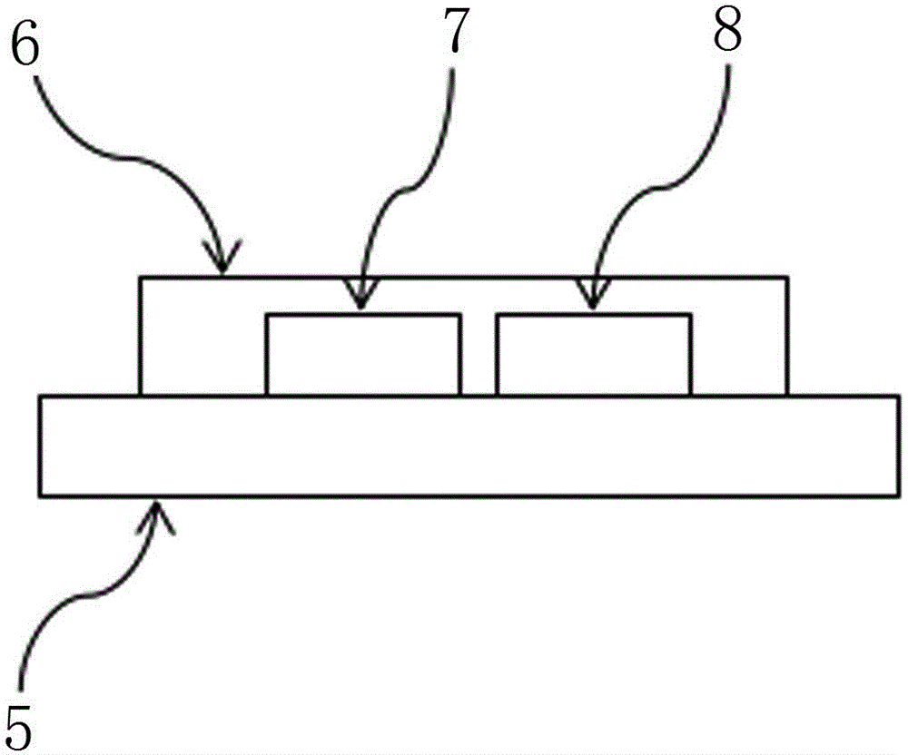
[0062] Example 2 Photoelectrochemical immunosensor based on organic electrochemical transistor


PUM

PropertyMeasurementUnit
Thicknessaaaaaaaaaa
Thicknessaaaaaaaaaa

Abstract

The present invention discloses a photoelectrochemical biosensor comprising an electrolytic cell, electrolyte provided in the electrolytic cell, an organic electrochemical transistor provided in the electrolytic cell, and a gate electrode provided in the electrolytic cell, wherein the organic electrochemical transistor comprises a substrate, a source electrode and a drain electrode disposed on the substrate, and an organic semiconductor thin film layer coating the substrate and connected with the source electrode and the drain electrode; the gate electrode is modified with a photoelectric active semiconductor material as a sensitive functional layer of the sensor. The photoelectrochemical biosensor of the invention has extremely high sensitivity, the structure is simple and the device size is small, and the problem that the photoelectrochemical biosensor is not easy to miniaturize is solved. The photoelectrochemical biosensor of the invention has universality in the field of biological detection, and can be widely applied in the biosensor field such as enzyme biosensor, cell biosensor and the like, besides applied to DNA sensor and immune sensor.

Description


Claims


Application Information

Patent Timeline
Owner SHENZHEN UNIV
Why Eureka
Try Eureka