Battery test clamp

A battery test and battery technology, applied in the field of fixture tooling, can solve the problems of unable to collect temperature signals, invisible installation positions, and unable to install batteries, etc., to improve test safety and reliability, facilitate line tracking and inspection, and clear wiring organized effect

Pending Publication Date: 2017-05-31
南京四象新能源科技有限公司
View PDF10 Cites 1 Cited by
  • Summary
  • Abstract
  • Description
  • Claims
  • Application Information

AI Technical Summary

Problems solved by technology

[0006] Existing test devices have the problem of low test efficiency. A set of devices usually only tests one battery, especially not suitable for batch testing of batteries in a constant temperature and humidity chamber. The test includes charging and discharging the battery, Voltage monitoring and temperature measurement, such as CN102967732 A, CN103825043 A
[0007] Most of the existing technologies cannot or are not suitable for charging and discharging power batteries, especially when using high current (above 1C) for charging and discharging
[0008] Chinese patent CN102967732A discloses a fixture for measuring internal resistance of a battery, such as figure 1 As shown, this invention is used to measure the internal resistance of batteries. This set of devices is not suitable for measuring multiple batteries at the same time, and because there is no limit at the bottom of the battery (the right boundary of the box in the figure), it depends entirely on the surface of the battery and the bearing plate 1 friction to ensure the contact between the test terminal 21 and the battery, in this case the contact resistance will be very large, and the device cannot be used to charge and discharge the battery
[0009] Chinese patent CN202502118U discloses a slide-type high-speed four-wire battery special measuring fixture, such as figure 2 As shown, this patent is relatively more suitable for batch measurement, but it is only suitable for batteries with electrodes separated at both ends. It is not suitable for batteries with electrodes on the same side. It cannot be used for charging

Method used


Image

  • Battery test clamp
  • Battery test clamp
  • Battery test clamp

Examples


Embodiment Construction

[0036] The present invention will be further described below in conjunction with the accompanying drawings. The following examples are only used to illustrate the technical solution of the present invention more clearly, but not to limit the protection scope of the present invention.

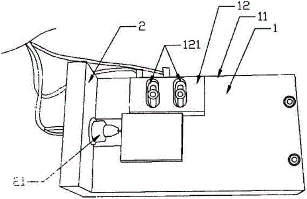
[0037] Figure 5 It is a structural schematic diagram of the present invention after installation. Figure 6 It is a schematic diagram of the disassembled structure of the present invention. The present invention includes a test base 1 and a battery clamping assembly 2, which are connected by screws 3 with pads. The test fixture of the present invention can be used in a constant temperature and humidity chamber (hereinafter referred to as a constant temperature chamber) or not in a constant temperature chamber, and the usage methods in the two cases are different. Firstly, the method of using the fixture in the incubator is introduced in detail. After the test base 1 is assembled first, it is f


PUM


Abstract

The invention discloses a battery test clamp which comprises a test base and a battery clamping assembly. The battery clamping assembly is arranged above the test base, and the bottom of the battery clamping assembly is connected with the top of the test base by fasteners. The battery test clamp has the advantages that a plurality of batteries can be tested by the single battery test clamp; probes of the battery test clamp are adaptive and can be in sufficient contact with battery terminals even under the conditions that the surfaces of the battery terminals are not perpendicular to the probes or the surfaces of the battery terminals are not sufficiently smooth, and the probes only have extremely low contact resistance; all the probes can be separated from one another, accordingly, the test safety and reliability can be improved, and short-circuit risks can be prevented; electric power and electronic cables are sufficiently and reasonably constrained and are clearly routed in order, and accordingly the battery test clamp can bring convenience to tracing and checking circuits; the battery test clamp not only can be used for testing square batteries, but also can be used for testing cylindrical batteries.

Description


Claims


Application Information

Patent Timeline
Owner 南京四象新能源科技有限公司
Why Eureka
Try Eureka